Zero crossing power regulator circuit
Although the zero-crossing power regulation circuit introduced in this paper is simple, it can work reliably. It is suitable for the power adjustment of various electric heating appliances and the power adjustment of series excited motor. For electrical staff reference.
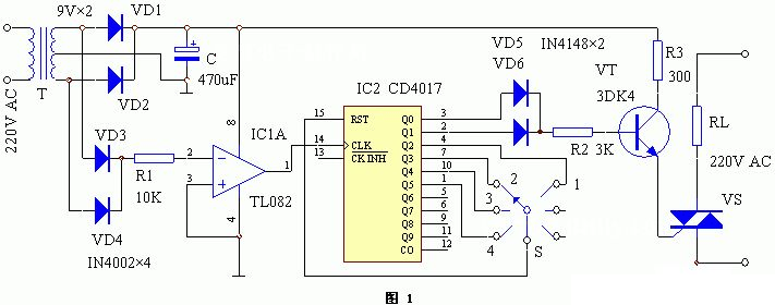
The circuit working principle of the device is shown in Figure 1. It is composed of power supply circuit, AC zero crossing detection circuit, decade counter/pulse distributor and bidirectional thyristor. After the 220V mains is reduced by the power transformer T, the full wave rectifier circuit composed of diodes VD1 and VD2 is rectified, and the C filter is fed to the whole machine circuit. After full wave rectification by diodes VD3 and VD4, the resulting pulsating DC voltage is added to the inverse input of the operational amplifier IC1 through R1. When the pulsating voltage crosses zero (that is, the AC voltage crosses zero), the IC1 will appear to cross zero pulse.
IC2 is used to count and distribute zero crossing pulses to generate a thyristor trigger signal. S is a power regulation switch, through which the IC2 counting mode is changed to adjust the power of the AC load. For example, when S is in the “3″ file, IC2 performs a quaternary count, and only 2 trigger pulses are generated for every 4 input zero crossing pulses to trigger bidirectional thyristor conduction, so the file is half power. Since IC2 has 10 outputs, the appropriate combination of these outputs can obtain different power levels. VT is connected to a high current switch, which can trigger high current of thyristor VS with different flow rates, so that it can work reliably.

IC1 uses general operational amplifier integrated circuits (such as LM324N, TL082, etc.). IC2 uses CD4O17. VT using 3DK4 or other medium power switching triode can be, β≥1OO. VS should be selected according to the current of the load, its voltage is not less than 600V, and the voltage value of the inductive load can be increased. T Adopts 2 ~ 3W power transformer, secondary electric pressure 9V. S is the power selection switch, the porcelain band switch can be selected. Other components have no special requirements, and can be selected according to the numerical figure.
A simple small power supply circuit
A simple small power supply circuit with a fully adjustable output voltage from the lowest possible voltage.
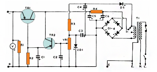
The transformer depresses the input AC to the desired low voltage AC, which is then rectified to the equivalent DC by a bridge rectifier.
The Zener diode ZD1 provides the required voltage regulation for the output. The bias of the Zener diode is obtained by D5 and associated components. C3 and C4 are used to filter out ripples.
VR1 works like a potential divider, enabling the user to apply the desired potential at the base of the TR2 transistor. Since TR1 and TR2 are connected as emitter followers, any voltage that occurs at the base of TR2 is copied to the collector of TR1.
This means that when VR1 is adjusted, the TR1 output also adjusts the equivalent voltage on the output terminal. However, since the minimum emitter pressure drop of a Darlington transistor is about 1.2V, the emitter output will always lag behind the 1.2V value, and a 1.2V drop will be displayed at the output end.
C1 and C2 act like electronic smoothing networks, helping to eliminate all kinds of interference and buzz in the circuit.
As a purely linear design, TR1 may show a lot of heat as the difference between input and output increases.
This means that if VR1 is adjusted to 3 V at the output and 24V at the input from the transformer, TR1 may consume a lot of power to compensate for the input/output difference.
The switch S1 was introduced to prevent this and to help control dissipation to a large extent. Therefore, when making lower output adjustments, it is recommended to switch S1 to the center tap to reduce the input/output difference by 50%, thereby reducing TR1 dissipation by 50%.
XuanGe Electronic Components Manufacturer
You may be interested in the following articles:
▶Infrared radiation alarm circuit
▶Energy saving LED flashlight circuit
▶Simple and practical LED light driver circuit
Post time: Jan-02-2025


