Flyback isolated transformer switching power supply, first of all, it is flyback, in line with the definition of “flyback”, that is, flyback is the switch tube cut-off, the transmission of energy; Secondly, it has an isolated transformer, this transformer plays an isolation role, and there will be a turn ratio, the turn ratio and the PWM duty ratio of the switching tube affect the output voltage. Whether AC/DC or DC/DC, the voltage reaching the transformer is actually a stable DC voltage. We know that only changes in voltage, similar to AC, can transfer energy through a transformer. We will use a switching tube to switch continuously to achieve a changing voltage at both primary ends of the transformer.
1. How does the transformer work
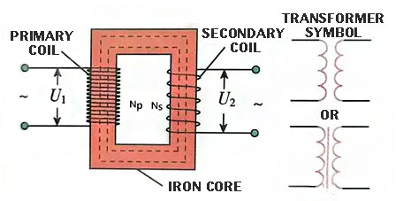
Construction of the transformer: consists of a closed iron core and two coils (or more) wound around the iron core, as shown in Figure 9.4.
Figure 9.3 Schematic diagram of transformer construction
The closed core is composed of laminated silicon steel sheets coated with insulating paint, and the coil is wound by insulated wire.
Primary coil: Coil connected to the input power supply, indicated in n₁ turns.
Secondary coil (secondary coil) : The coil connected to the load, the number of turns expressed by n₂.
The working principle of the transformer
(1) Mutual inductance is the basis of transformer work. The size and direction of the current in the original coil are constantly changing, and the magnetic field excited in the iron core is also constantly changing, and the changing magnetic field generates induced electromotive force in the secondary coil.
(2) The role of the primary and secondary coils
The primary coil acts as a load in the loop in which it is located, and the secondary coil acts as a power source in the loop in which it is located.
(3) Energy conversion proces
The transformer through the closure of the iron core, the use of mutual induction phenomenon to achieve the conversion of electrical energy (U, I₁) to magnetic field energy (changing magnetic field) and then to electrical energy (U₂, 1₂).
2, the working process of the switch tube switch
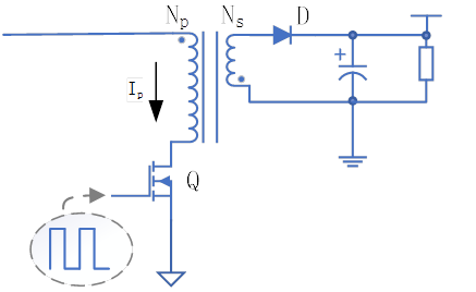
In the first state, when the PWM signal is at high current level, Q is switched on, as shown in the figure. Because the input voltage is added to the primary winding of the high-frequency transformer through the switching tube, there is current PI flowing through the primary side, and because the voltage polarity of the same name terminal on the secondary side of the transformer is negative, the rectifier diode VD is cut off, and the energy cannot be transmitted to the secondary winding. It can only be stored in the primary winding and discharged from the output capacitance to the load.
Figure 9.3 State diagram of the flyback switch power switch turned on
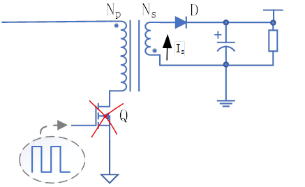
In the second state, when the PWM signal Is at low current level, Q is cut off, as shown in the figure, no current flows through the primary side, and the secondary side will generate current IS. According to the principle of electromagnetic induction, at this time, the induction voltage will be generated in the primary winding of the high-frequency transformer, so that the secondary winding will produce a voltage Us whose polarity is positive and negative, so the rectifier diode VD is switched on, and then the energy is output to the output end after the VD and C rectification filter. By adjusting the opening/closing time of the switch tube, the output voltage can be kept constant.
Figure 9.4 State diagram of the flyback switch power switch turned off
Flyback converter has the following main features:
(1) The polarity of the winding on both sides of the high-frequency transformer is heteronymous, and the eponymous end of the primary winding is connected to the positive end of the input power supply, and its heteronymous end is connected to the drive end of the power switch tube.
(2) High-frequency transformers can both play the role of energy storage, and can play the role of energy transmission.
(3) As long as the turn ratio of the high-frequency transformer meets the requirements, the output voltage can be higher or lower than the input voltage.
(4) Flyback converter design is flexible, by adding the number of transformer secondary winding output, you can form a multi-terminal output.
(5) Under normal circumstances, flyback converters do not need, and can not be connected in series between the output filter capacitor and the rectifier diode low frequency inductors. One less inductance component than the forward converter.
(6) Can work in continuous mode or non-continuous mode.
Each flyback transformer output is isolated from the primary side. Flyback converters are widely used in low-power switching power supply applications. Buck and Boost converters do not use transformers, are non-isolated converters, and cannot achieve multiple outputs, so neither is considered. The forward converter uses a transformer and is isolated, but the forward transformer has no way to meet the requirements of energy storage, and the forward converter is generally used in switching power supplies that require large output power, and the requirements for MOS tubes are more stringent. Flyback converters include high-frequency transformers, the output and input can be isolated from each other, and by increasing the number of output windings, to reach the requirements of multi-terminal output, more used in switching circuits with small output power.
Recommended articles:
▶ Working principle of switching power supply + circuit diagram analysis
▶ What is no-load/load operation of high-frequency transformer?
▶ Why is the switching power supply using a high-frequency transformer small in size?
▶ What if MOS is overcharged when switching power supply cuts load? Try this method!
Disclaimer: This article is a reprint article, reprint this article to convey more information, copyright belongs to the original author.
Post time: Nov-12-2024


