1. Overview of Switching Power Supply
Switching power supply is a high-frequency electrical energy conversion device, also known as switching power supply or switching converter. It switches the input voltage into a high-frequency pulse signal through a high-speed switching tube, and then converts the electrical energy from one form to another through the processing of transformer, rectifier circuit and filtering circuit, and finally obtains a stable low ripple DC voltage for power supply.
Switching power supply has the advantages of high efficiency, good stability, small size, light weight, high reliability, and can be adapted to different equipment power needs.
Switching power supply has been widely used in various fields, including industrial automation, communications and new energy. In the field of industrial automation, switching power supply provides stable power support for various automation equipments to ensure the efficient and stable operation of the equipments.
In the field of communication, switching power supply is widely used in wireless base station, network equipment, etc., to ensure the signal transmission stability of the communication system and improve the communication quality. In the field of new energy, switching power supply plays a key role in solar and wind energy systems, helping the effective use of renewable energy.
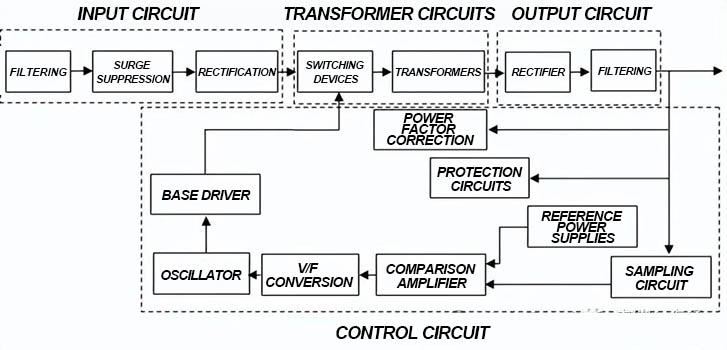
Switching power supply is roughly composed of four main components: input circuit, converter, control circuit, and output circuit. The following is a typical switching power supply schematic block diagram, mastering it is important for us to understand the switching power supply.
2. Classification of switching power supplies
Switching power supplies can be classified according to different classification standards. The following are several common classification methods:
1. Classification by input power type:
AC-DC switching power supply: converts AC power into DC power.
DC-DC switching power supply: converts DC power into another DC voltage.
2. Classification by working mode:
Single-ended switching power supply: has only one switch tube, suitable for low-power applications.
Dual-ended switching power supply: has two switch tubes, suitable for high-power applications.
3. Classification by topology:
According to the topology, it can be roughly divided into Buck, Boost, Buck-Boost, Flyback, Forward, Two-Transistor Forward, Push-Pull, Half Bridge, Full Bridge, etc. These classification methods are only part of them. Switching power supplies can also be classified in more detail according to other specific requirements and applications.
Next, we will introduce the commonly used Flyback and Forward. Forward and flyback are two different switching power supply technologies. Forward switching power supply refers to a switching power supply that uses a forward high-frequency transformer to isolate the coupled energy, and the corresponding flyback switching power supply is a flyback switching power supply.
2.1 Forward switching power supply
Forward switching power supply in the structure is more complex, but the output power is very high, suitable for 100W-300W switching power supply, generally used in low-voltage, high-current switching power supply, more widely used.
As shown in the figure below, for forward switching power supply specifically when the switching tube is turned on, the output transformer acts as a medium directly coupled to the magnetic field energy, electrical energy and magnetic energy are converted to each other, so that the input and output at the same time.
There are also shortcomings in the daily application: such as the need to increase the reverse potential winding (to prevent the transformer primary coil generated by the reverse potential to the switching tube breakdown), the secondary more than one inductor for energy storage filtering, so compared to the flyback switching power supply, its cost is higher, and forward switching power supply transformer volume than the volume of the flyback switching power supply transformer is larger.
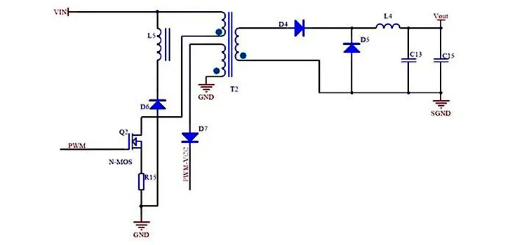
Forward switching power supply
2.2 Flyback switching power supply
As shown in the figure below, a flyback switching power supply refers to a switch power supply that uses a flyback high-frequency transformer to isolate the input and output circuits. Its transformer not only plays the role of converting voltage to transmit energy, but also plays the role of energy storage inductor. Therefore, the flyback transformer is similar to the design of an inductor. All circuits are relatively simple and easy to control. Flyback is widely used in low-power applications of 5W-100W.
For a flyback switching power supply, when the switch tube is turned on, the current of the primary inductor of the transformer rises. Since the output coil of the flyback circuit has opposite ends, the output diode is turned off, the transformer stores energy, and the load is supplied with energy by the output capacitor. When the switch tube is turned off, the inductive voltage of the primary inductor of the transformer is reversed. At this time, the output diode is turned on, and the energy of the transformer is supplied to the load through the diode, while charging the capacitor.
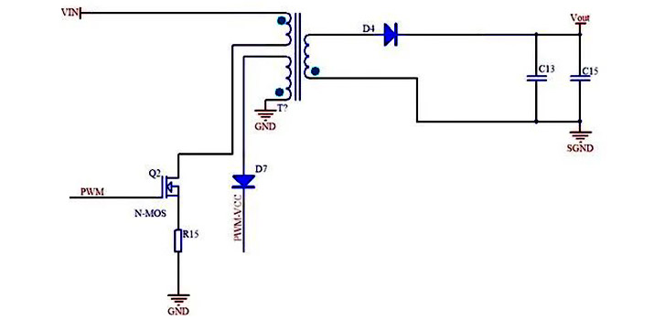
Flyback switching power supply
From the comparison, it can be seen that the transformer of the forward excitation only has the function of transformer, and the whole can be regarded as a buck circuit with transformer. Flyback transformer can be regarded as an inductor with a transformer function, is a buck-boost circuit. In general, the forward flyback working principle is different, forward is the primary work secondary work, the secondary does not work with a current inductor to renew the current, generally CCM mode.
Power factor is generally not high, and the input and output and variable duty cycle is proportional. Flyback is the primary work, the secondary does not work, the two sides independently, generally DCM mode, but the inductance of the transformer will be relatively small, and the need to add air gap, so usually suitable for small and medium power.
Forward transformer is ideal, no energy storage, but because the excitation inductance is a finite value, the excitation current makes the core will be large, in order to avoid flux saturation, the transformer needs auxiliary winding for flux reset.
Flyback transformer can be seen as a form of coupled inductance, inductance first energy storage and then discharged, due to the flyback transformer’s input and output voltages opposite polarity, so when the switching tube is disconnected, the secondary can provide the magnetic core with a reset voltage, and thus the flyback transformer does not need to add additional flux reset winding.
Post time: Sep-29-2024