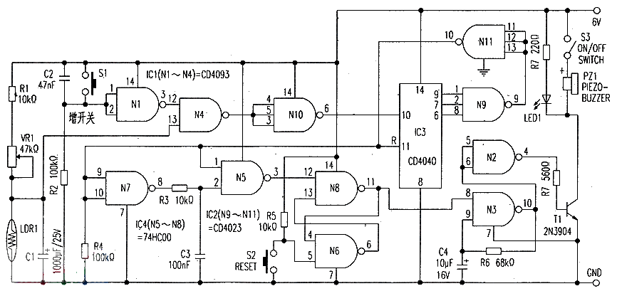
The circuit shown in the picture is one that works on a seven-day weekly cycle. You can switch S1 on the diagram within seven days. Select a day as a reminder day. In order to remember a particular job, event or other important thing that should be done that day, the circuit’s reminder mode is constantly shining for LED1.
The circuit uses a photoresistor (LDR1) to detect the rising sun. When the sun rises. The ambient light intensity reduces the resistance of LDR1, resulting in a decrease in the level of the input (13) pin with the non-gate N4. Since the other pin (12) of N4 is high, the result with the output ⑥ pin of non-gate N10 becomes low. Make counter IC3 do a count. Into the evening. The LDR1 resistance value is increased, so that the N4 (13) pin is reset to the high level, the result is that the ⑥ pin of N10 is reset to the high level, IC3 waits to trigger again, every day, IC3 is counted according to the above method. With this method of counting, IC3 starts a count every morning. Until seven days later.
On the morning of the seventh day, all inputs to the gate N9 are switched to high, resulting in the output of the N9 being switched to low. The output pin of the N11 switches the low level of the N9 output to the high level. The high level is used to trigger the pulse generator composed of N7 and N5. Cause it to produce a narrow pulse.
This narrow pulse in turn triggers a flip-flop composed of N8 and N6, resulting in a high level generated by the flip-flop that causes the multivibrator composed of N3 gate (astable) to oscillate. The multivibrator has an oscillation frequency of 2Hz and drives T1 through the N2 gate. Make LED1 flash and glow. As a reminder of Sunday. LED1 constantly flashes, and only press the S2 reset switch to stop blinking.
The relevant logic functions of the circuit are as follows:
Once the enable end (input ⑧ pin) of the non-gate N3 is low, the output of the multivibrator remains at a high level. At this time. Transform this high level to a low level with the non-gate N2. That is, the output of N2 is low. Transistor T1 is no longer on, so LED1 no longer flashes (the multivibrator is blocked).
The (11) pin R of the counter IC3 is the reset terminal (high level reset), which in turn is connected to the output terminal of N11, and on the seventh day, when the ⑩ of N11 becomes high, IC3 will be reset. Once IC3 is reset. Its output becomes low. Wait for the next week’s count.
For example. If you need a reminder the last four days of next week. First, cover the light of the sensor LDR1 with your hand. Then press the switch S1 three times. At this point your reminder can count from day 4.
The attached circuit is installed on a common printed board (PCB), and then the PCB board is installed in a small box. When using the reminder, first turn on the power, at this time LDE1 will glow. Press the reset switch S2 again to make LED1 stop blinking. After covering the light of LDR1 with your hand, press switch S1 several times until LED1 begins to blink again, at which time the counter IC3 starts to count from 0, and immediately press the reset switch S2 to stop LED1 blinking.
After the above Settings are complete. The counter IC3 will count from the day after the setup is complete, and after six days, LED1 will shine.
Note: When the reminder is working normally, the photoresistor (sensor)LDR1 must be placed in the brightest place in the room. To ensure that LDR1 works normally at sunrise and sunset (LDR1 resistance becomes low at sunrise, and LDR1 resistance is high at sunset night).
Post time: Dec-11-2024


