The high-speed maglev train operated in Shanghai is a TR08 maglev train imported from Germany, which uses a long-stator linear synchronous motor and a constant-current conduction levitation system. Its traction power supply system is shown in Figure 1, and consists of main components such as a high-voltage transformer (110kv/20kv), an input transformer, an input converter, an inverter, and an output transformer.
The traction power supply system of the maglev train is converted from the 110kv grid voltage to 20kv through a high-voltage transformer, and then converted to a DC voltage of ±2500v by the input transformer and the input converter. The DC voltage from the DC link is converted into three-phase AC power with variable frequency (0~300Hz), variable amplitude (0~×4.3kv), and adjustable phase angle (0~360°) by a three-phase three-point inverter. The traction converter of the maglev train has two working modes:
(1) The direct output mode of the inverter pulse width modulation is the output mode when the motor works at a low frequency, with a switching frequency of 0~70Hz. At this time, two sets of three-point inverters are connected in parallel, and the output is connected through the primary winding of the output transformer as shown in Figure 1. At this time, the primary winding of the output transformer is equivalent to a parallel balancing reactor, and also plays a filtering role.
(2) Transformer output mode is the output mode when the motor works at high frequency, with a switching frequency of 30Hz~300Hz. At this time, the two sets of inverters in the main traction converter are connected in series to the primary side of the output transformer, and the output is output after the output transformer boosts the voltage.
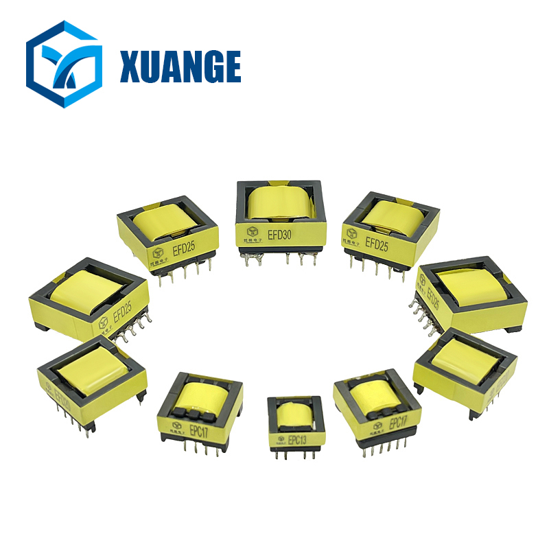
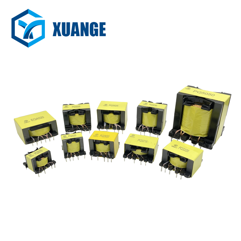
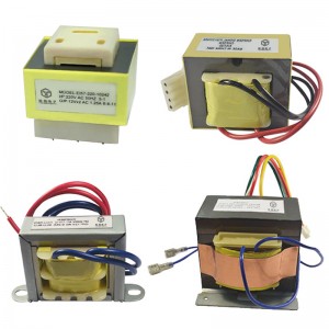
EFD transformer EI transformer PQ transformer
3.1 Input converter
The front stage of the input converter consists of a high-voltage transformer and an input transformer. The input transformer consists of two rectifier transformers, whose function is to reduce the high-voltage grid voltage through the secondary transformer and then send it to the input converter. For large-capacity high-voltage rectifier transformers, in order to improve the rectification efficiency, two sets of 6-pulse rectifier bridges are used. Each set of rectifier transformers is powered by two sets of three-phase windings, one y junction and one d junction. The static converter system adopts a scheme of three single-phase three-winding transformers, which are connected to form the y/y, d group rectifier transformer scheme shown in Figure 2 through the prescribed connection of each winding. Its main advantages are:
(1) Small spare capacity, more economical;
(2) Small single capacity, easier to meet the transportation requirements for the device size;
(3) The three windings can be arranged on the same core column, which helps to reduce the harmonic loss of the transformer.
In order to control the DC link voltage of the intermediate circuit and reduce the grid-side excitation, each rectifier of the system is composed of a six-pulse three-phase fully controlled rectifier bridge and a six-pulse three-phase uncontrolled rectifier bridge in series, as shown in Figure 2. In this way, the two sets of rectifiers are connected in series, and the middle point is grounded through a high resistance (as shown in Figure 1), forming a three-potential intermediate circuit DC link. The voltage of the DC link is controllable, ranging from 2×1500V to 2×2500V, and the rated current is 3200A. In order to obtain a smooth DC current, a smoothing reactor is connected in series in the intermediate circuit. At the same time, in order to prevent the rectifier bridge and DC link from overvoltage, DC side overvoltage protection is adopted. In the DC link intermediate circuit, there are thyristors and high-power resistors with discharge protection as DC side absorption devices to suppress overvoltage. In addition, the intermediate point of the DC link of the intermediate circuit is grounded through high resistance protection and has a ground fault display.
3.2 Traction inverter
(1) Inverter structure
The structure of one phase in the three-phase inverter of Shanghai Maglev Train is shown in Figure 3. The main tube adopts GTO full-control device. The main circuit adopts two main tubes in series with a clamping diode at the midpoint. This circuit is also called a three-point (or three-level midpoint embedded) inverter. This can reduce the main tube withstand voltage by half. At the same time, under the same switching frequency and control mode, the harmonics of its output voltage or current are less than those of the two-level, and the common-mode voltage generated by the output voltage at the motor end is also less, which is beneficial to extend the service life of the motor.
The four main tubes of each phase bridge arm have three different on-off combinations, and output different voltages respectively (see Table 1). The peak voltage of the main GTO is 4.5kV, and the peak current is 4.3ka. The three-point inverter requires that the main V1 and V4 cannot be turned on at the same time, and the control pulses of V1 and V3, V2 and V4 are mutually opposite. In addition, the above main on-off conversion must comply with the principle of first off and then on.
The three-level inverter is developed on the basis of the two-level inverter. The introduction of the mature control technology of the two-level inverter into the three-level inverter has formed a variety of inverter control strategies. At present, the more mature control strategies used for three-level inverters are: single pulse control method, upper and lower dual modulation wave SPWM control method, 120° conduction PWM control method, 90° phase staggered PWM control method, neutral point potential deviation suppression PWM control method, switching frequency optimal PWM control method, specific low-order harmonic elimination method (SHEPWM), three-level inverter voltage space vector control method (SVPWM) and neutral point potential deviation suppression voltage space vector control method [2,3].
(2) GTO drive circuit
High-power GTO drive circuit must first solve the problems of isolation and anti-interference. The trigger pulse signal of GTO in the main traction inverter of Shanghai Maglev Train is transmitted by optical fiber cable, so the problems of isolation and anti-interference are solved, thereby ensuring the accuracy of GTO trigger pulse and indirectly ensuring the driving safety of Maglev Train. In addition, the key to whether the high-power GTO drive circuit can work normally lies in the power supply. The amplitude of GTO gate trigger pulse should be high enough, and its leading edge should be steep, while the trailing edge should be gentler. To meet this requirement, the gate drive power supply of GTO in the main traction inverter of Maglev Train is 45V/27A, and the trailing edge signal and voltage signal of GTO trigger pulse are sent back to the control system. In addition, the main traction inverter of Shanghai Maglev Train adopts a variety of protections: overvoltage protection of brake circuit breaker, overcurrent protection current limit, pulse interruption and ground fault detection.
(3) Absorption circuit
There are many absorption circuits of GTO. The absorption circuit of the three-level main traction inverter of Shanghai Maglev Train is shown in Figure 3. The absorption circuit must ensure that the di/dt and du/dt of the GTO do not exceed the specified allowable values when it is working. In this way, the absorption circuit of the GTO must have an inductor and a capacitor C. In Figure 3, the inductors L1, L2 and the GTO are connected in series to limit the di/dt of the GTO. The diodes D11, D12, the resistor R1 and the inductor L1 form the energy release circuit of the inductor itself. The capacitors C11 and C12 are used to limit the du/dt of the GTO, and the diodes D12 and D13 form the energy release circuit of the capacitor. Compared with the RCD absorption circuit, the above absorption circuit adds a large capacitor C12, so the turn-off absorption capacitor C11 is half of the capacitance value of the RCD absorption circuit, so the loss is also reduced by half; at the same time, the capacitor C12 plays a voltage clamping role, which is used to suppress the turn-off overvoltage of the GTO. For a 1500kva inverter, the loss of this absorption circuit is roughly the same as that of the asymmetric absorption circuit.
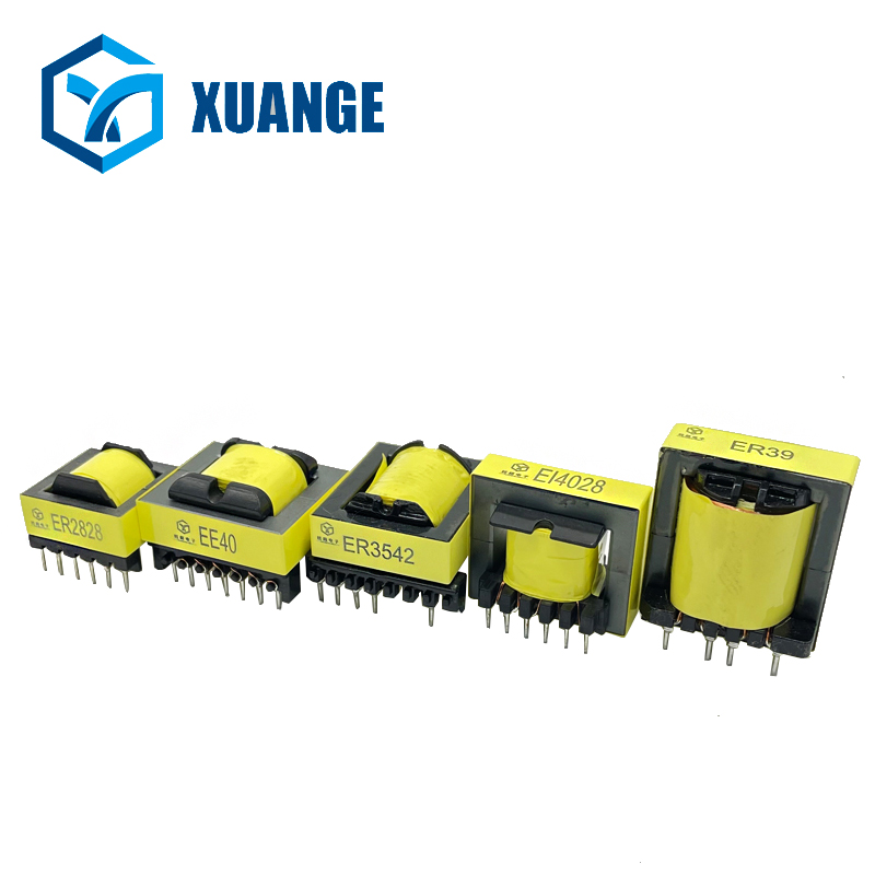
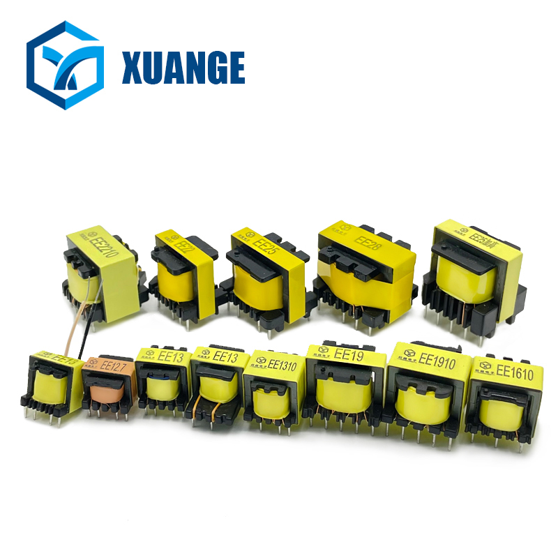
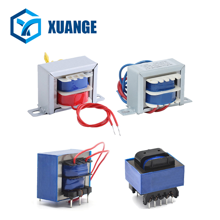
ER Type Transformer Coupling type transformer 5V-36V Ferrite Core Transformer
4 Conclusion
The traction power supply system of Shanghai high-speed maglev train has the following characteristics:
(1) It adopts high-speed conventional linear synchronous motor. The whole traction power supply system is placed on the ground and is not limited by the space of the vehicle body, which is conducive to the most effective three-step power supply method;
(2) It adopts the neutral point clamped three-level converter technology suitable for high-voltage and high-power occasions, avoiding the direct series connection of GTO thyristors, so that the capacity of high-power power electronic devices can be fully utilized;
(3) Two sets of adjustable 12-pulse rectifier bridges are used in the input converter, which not only reduces harmonics and interference, but also suppresses the deviation of the midpoint potential;
(4) Thyristors and GTOs use optical fiber cables to transmit pulse signals, which has high anti-interference performance. The power supply and traction control system is one of the keys to control the safe and stable operation of maglev trains. Its principle and structure need further research and analysis.
Zhongshan XuanGe Electronics Co., Ltd. is a manufacturer specializing in the R&D, production and sales of high and low frequency transformers, inductors andLED driver power supplies.
The company originated in Shenzhen, the forefront of China’s reform and opening up, and was established in 2009. Over the years, we have continued to grow and develop. By 2024, we have 15 years of experience in producing high frequency transformers, and our sophisticated experience has made XuanGe Electronics enjoy a good reputation in domestic and foreign markets.
We accept OEM and ODM orders. Whether you choose a standard product from our catalog or seek customization assistance, please feel free to discuss your procurement needs with XuanGe, the price will definitely satisfy you.
William (General Sales Manager)
186 8873 0868 (Whats app/We-Chat)
E-Mail: sales@xuangedz.com
liwei202305@gmail.com
Post time: May-30-2024