Magnetization of the core of a single-excitation switching power supply transformer by pulse train part1
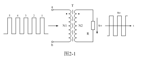
For simplicity, we equivalent the single-excited transformer switching power supply to the circuit shown in Figure 2-1, where we regard the DC input voltage through the control of the switch on and off as a series of DC pulse voltage, that is, unipolar pulse voltage, directly to the switching transformer power supply. Here we especially call the transformer a switching transformer, to show that the circuit shown in Figure 2-1 is different from the general power transformer circuit in terms of working principle.
In the general power transformer circuit, when the input voltage at both ends of the power transformer is 0, it means that the input end is short-circuited, because the internal resistance of the power supply can be seen as 0; In the switching transformer circuit, when the input voltage at both ends of the switching transformer is 0, it means that the input end is open, because the internal resistance of the power supply can be seen as infinite.
In Figure 2-1, when a group of serial numbers 1, 2, 3,… When the DC pulse voltage is added to both ends of the primary coil a and b of the switching transformer, there will be an exciting current flowing through the primary coil of the switching transformer, at the same time, a magnetic field will be generated in the core of the switching transformer, and a magnetic field line flux with a magnetic flux density of B will be generated under the magnetic field with a magnetic field strength of H, referred to as the magnetic flux, expressed by “Φ”.
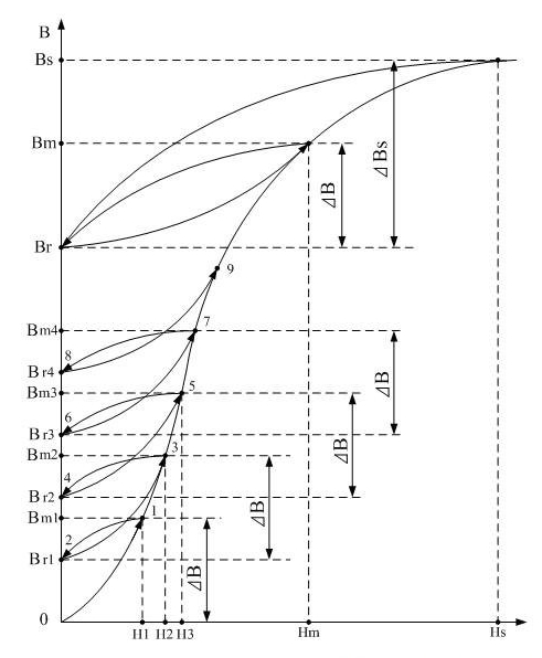
In the transformer core, the process in which the flux density B or flux Φ is changed by the action of the magnetic field strength H is called the magnetization process; Therefore, the curve used to describe the corresponding change between the magnetic flux density B and the magnetic field strength H is called the magnetization curve. Figure 2-2 shows the relationship between magnetic flux density B and magnetic field strength H when the core of a single-excitation switching transformer is magnetized.
By the way, it is pointed out that in the process of analyzing the magnetization of the transformer core, the two names of magnetic flux density and magnetic induction intensity are often used, and the two names are not different in nature, and can be common to each other, and different names are used in different occasions, just for convenience of use.
If the core of the switching transformer has never been magnetized by any magnetic field before, and the volt-second capacity of the switching transformer is large enough, then when the first DC pulse voltage is added to both ends of the transformer primary coil a and b, there will be an exciting current flowing through the transformer primary coil and a magnetic field will be generated in the transformer core.
Under the action of the magnetic field strength H, the magnetic induction strength B in the transformer core will rise according to the 0-1 magnetization curve in Figure 2-2. When the first DC pulse voltage is about to end, the magnetic field intensity reaches the first maximum value Hm1, and the magnetic induction intensity will be magnetized to the first maximum value Bm1 by the magnetic field intensity. This results in a magnetic induction increment ΔB, ΔB = Bm1-0. The magnetic induction strength increases, indicating that the magnetic field generated by the excitation current flowing through the transformer primary coil is magnetizing the transformer core.
When the sequence pulse voltage is added to both ends of the primary coil a and b of the switching transformer, the magnetic field generated in the transformer core is entirely generated by the excitation current flowing through the primary coil of the transformer. The excitation current flowing through the primary coil of the transformer is:
In formula (2-8), iμ is the exciting current flowing through the primary coil of the transformer, E is the voltage added to both ends of the primary coil of the transformer, L1 is the inductance of the primary coil of the transformer, t is the time, iμ(0) is the initial current, that is, the exciting current flowing through the primary coil of the transformer when t = 0.
If the duty cycle factor (duty cycle) of the pulse train meets that the magnetizing current drops to zero before the entry of the last pulse, that is, the switching power supply works in the current critical continuous or discontinuous state.
After the end of the first DC pulse, because the primary coil of the switching transformer is open, although the excitation current flowing through the primary coil of the transformer drops to zero, the magnetic field strength H will not drop to zero immediately; At this time, the primary and secondary coil of the transformer will produce a counter-electromotive force at the same time, due to the role of the counter-electromotive force, there will be current flowing in the primary and secondary coil loop of the transformer, this circuit current belongs to the induced current, or induced current.
When the first DC pulse ends, if the primary coil of the switching transformer is not open, the back electromotive force will reverse charge the input voltage. If the primary coil of the switching transformer is open, the back electromotive force will charge and discharge the distributed capacitance in the primary coil, which will produce high frequency oscillations inside the primary coil.
The induced current generated by the back electromotive force will generate a reverse magnetic field in the transformer core, so that the transformer core is demagnetized, and the magnetic field intensity H gradually decreases from the first maximum value Hm1 to 0. However, the magnetic flux density B in the transformer core does not return to the original 0-1 magnetization curve at the time of magnetization, and follows the magnetic field strength down to zero, but returns to 2 points according to another new magnetization curve 1-2.
That is: the first residual magnetic flux density Br1. Therefore, people are used to the value of the magnetic flux density at 2 points, called the residual magnetic flux density, or referred to as “remanence”. The remanence of the transformer core indicates that the transformer core has memory characteristics, which is the basic characteristic of ferromagnetic materials.
Post time: Nov-27-2024


