A variety of household appliances, industrial frequency transformers, whether they design their own winding, or repair the burnt out transformer, are involved in part of a simple calculation, textbooks on the formula, although rigorous, but the practical application of the complexity, not very convenient. This article introduces the practical transformer calculation of the empirical formula.
1. Iron core selection
According to their own power needs to choose the right core is the first step in winding the transformer. If the iron core (silicon steel sheet) selection is too large, will lead to an increase in the size of the transformer, the cost of higher, but the iron core is too small, will increase the loss of the transformer, while the ability to carry the load becomes poor.
In order to determine the size of the iron core, the first thing to calculate the actual power consumption of the transformer secondary, which is equal to the transformer secondary winding voltage, the sum of the product of the load current. If it is a full-wave rectifier transformer, it should be calculated as 1/2 of the transformer secondary voltage. Secondary winding power consumption to join the transformer itself loss power, that is, the transformer primary apparent power.
General secondary winding power in the 10w below the transformer, its own loss of secondary power consumption can be up to 30 ~ 50% of the actual power consumption, its efficiency is only 50 ~ 70%. Secondary winding power in the 30 w below loss of about 20 ~ 30%, 50 w below loss of about 15 ~ 20%, 100 w below loss of about 10 ~ 15%, 100 w above loss of about 10% below, the above loss parameter is about the ordinary plug type transformer. If the order of R-type transformer, c-type transformer and toroidal transformer is followed, the loss parameter decreases in turn.
Based on the total primary power of the transformer calculated above the core can be selected. Iron core area S = a x b (cm2). As shown in the attached figure. Transformer apparent power and the relationship between s with the following empirical formula: s = K √ P1
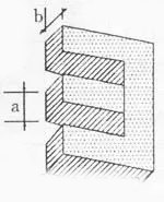
P1 for the transformer primary total apparent power, unit: VA (volt-ampere), s should be selected core cross-sectional area, K is a coefficient, with the size of the transformer Pl different selection of different values. At the same time, taking into account the silicon steel sheet between the insulating paint, the effect of the gap, K and P1 relationship is:
P1 K value
10VA 2~2.2
50VA below 2 ~ 1.5
lOOVA below 1.5 ~ 1.4
2. Calculation of turns per volt
After selecting the core s. Then determine the number of turns per volt, in order to wind the transformer has a reasonable excitation current. Commonly used empirical formula: N = (40 ~ 55)/S, N is the number of turns per volt.
According to the different quality of silicon steel sheet selection coefficient 40 ~ 55. more advanced high silicon steel, with the eye to observe the surface of the scales of crystallization. And extremely brittle, only 1 to 2 times that breaks, broken at the uneven, the coefficient is taken as 40. If the silicon steel sheet surface is clean, bending 4 to 5 times is still not easy to break, the section for the neat straight line, the coefficient is taken as more than 50.
Find out the number of turns per volt multiplied by 220V that is the primary turns, multiplied by the number of secondary voltage requirements that is the secondary winding turns. Because the wire has a resistance, current flow through the voltage drop, the secondary turns should be increased by 5 ~ lO% (according to the load current selection, the current can be increased by a larger proportion).
3. Selection of wire diameter
According to the size of the winding load current, select different diameters of enameled wire. The following empirical formula can be used to find out:
d=O.8√I.
Unit: l – A. d (wire diameter) – mm.
4. Winding Methods and Precautions
So, nowadays, the insulation strength of enameled wire has really improved. For small power transformers around 50W, we usually go with a flame-retardant plastic skeleton and stack the windings. Just make sure to use high-strength enameled wire, and when you’re winding it up, keep everything lined up layer by layer—no big diagonal spans allowed! This helps avoid increasing the voltage difference between wires. For transformers over 50W, since there are fewer turns per volt, the voltage difference between wires gets higher. It’s best to put down insulating paper (like 0.05mm thick cable paper or kraft paper) for each layer as you wind it.
You definitely want to prevent any upper layers from slipping into lower ones! The insulation between windings should depend on how much voltage you’re dealing with. Between primary levels, aim for at least four layers of 0.1mm cable paper—skip using self-adhesive tape here! If your small transformer has more than two groups of secondary windings stacked together, make sure to add two layers of cable paper insulation between each group too. And if this transformer is going into audio or audiovisual gear? Don’t forget to include some electrostatic shielding padding in those multi-layer setups. After you’ve done all that winding stuff, pay attention when inserting silicon steel sheets—they need to fit snugly so you don’t get electromagnetic noise messing things up.
Whether it’s double E-shaped or EI-shaped sheets, they should be tightly packed together without gaps; crossing them can help too! When you’re putting in those last few pieces (about four or five), do it from the center so you don’t damage any wiring bundles along the way. Then let’s dry it out and dip it in paint afterward! For transformers under 50W, you can use an endothermic drying method: short-circuit all secondary windings first and then connect a light bulb (60 ~ 100W / 220V) in series with mains power so that it warms itself automatically.The larger the bulb, the higher the temperature, but in a closed state, so that the temperature is below 80 degrees is safer.
Post time: Sep-25-2024