LED lighting set low power consumption, long life and other advantages, is becoming increasingly popular. With the continuous decline in prices, LED has begun to be applied in home lighting. Recently contacted several commercially available 36-head, 60-head LED lights, power consumption is only about 3w, brightness equivalent to 10w incandescent lamps, very power-saving.
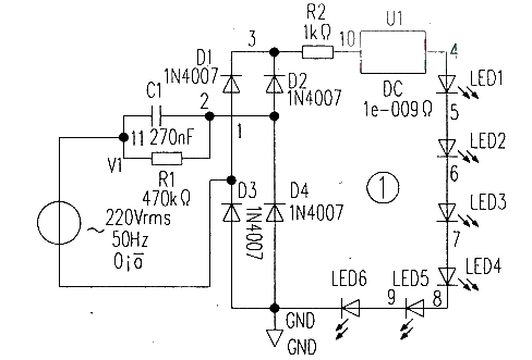
However, after a period of use, it was found that the light decay was more serious. After disassembly, the circuit is shown in Figure 1, which is very simple, and all capacitor step-down circuits are used. Although the capacitor step-down belongs to the constant current power supply, the capacitor is equivalent to a short circuit at the beginning of the moment, the current changes greatly, and the current changes greatly when the grid voltage changes substantially.
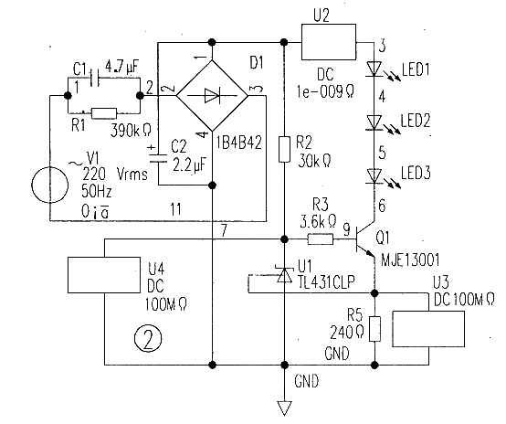
The measured current is as follows: the current is 13mA at 180v, 17mA at 220V and 19mA at 250v. It is the wide range of current changes that lead to LED light decay. In order to find a solution, the author consulted some LED driver circuits, but professional LED driver integrated circuits are very expensive, and most of them are low-voltage DC/DC power supply methods. To this end, the author designed a simple constant current source LED driver circuit, through the electronic circuit simulation and actual circuit experiment, the effect is very good. The circuit is shown in Figure 2.
Figure 1
C1, R1, D1, C2 constitute the AC/DC conversion circuit, where C=1/2πf U=(0.0000145)I, the unit is farad. If I=10mA, C1=0.15μF, C1 is actually selected as the Urm of 0.47uF. D1 rectifier bridge ≥400v, or 4 1N4004 or IN4007 rectifier diodes are selected to form the rectifier bridge: filter capacitor C2 is selected as 2.2uF ~ 4.7uF electrolytic capacitor with 400V withstand voltage. The constant current source circuit is composed of R2, U1, R3, R5 and Q1. Q1 is the MJE13001. R5 is the current sampling resistance of the voltage resistant UceBR≥40DV, and it is also the current negative feedback resistance of Q1. Adjusting the size of R5 can change the working current of the LED, thus changing the brightness port Io=Uref/R5=2.5/R5, and the ID=10mA when R5=240Ω.
Here’s how it works. If the input voltage increases, the output current Io increases, and the voltage Ur5 on R5 causes the voltage rise of TL431① foot to change, so that the anode current of TL431 increases, Uk decreases, so that the base voltage of triode Q1 decreases, Ube decreases resulting in Ic decreases, so as to keep the current flowing through the LED unchanged, to achieve the purpose of constant current.
Waterproof power supply switching power supply LED Ultra-thin Power Supply
After the design of the above circuit was completed, Multisim 10 software was used for simulation. When the input voltage varied between 180v and 250v, the current remained unchanged at 10mA. The result was shown in Figure 2. After the simulation, the circuit is installed on the universal board for actual debugging, and the results are similar to the simulation. Through continuous work experiment, the effect is good. The circuit is simple, low cost and cost-effective.
Figure 2
The copyright of the content (articles, pictures, videos) reproduced on this website belongs to the original author.
Post time: Dec-04-2024

