Common mode inductors,are often used in computer switching power supplies to filter common mode electromagnetic interference signals. In the board design, the common mode inductor also plays the role of EMI filtering, which is used to suppress the outward radiation and emission of electromagnetic waves generated by high-speed signal lines.
As an important component of magnetic components, inductors are widely used in power electronic circuits. It is an indispensable part especially in power circuits. Such as electromagnetic relays in industrial control equipment and electric power meters (watt-hour meters) in power systems. Filters at the input and output ends of switching power supply equipment, tuners at the TV receiving and transmitting ends, etc. are all inseparable from inductors. The main functions of inductors in electronic circuits are: energy storage, filtering, choke, resonance, etc. In power circuits, since the circuits deal with energy transfer of large currents or high voltages, inductors are mostly “power type” inductors.
Precisely because the power inductor is different from the small signal processing inductor, the topology of the switching power supply is different during the design, and the design method also has its own requirements, causing design difficulties. Inductors in current power supply circuits are mainly used for filtering, energy storage, energy transfer, and power factor correction. Inductor design covers many aspects of knowledge such as electromagnetic theory, magnetic materials, and safety regulations. Designers need to have a clear understanding of the working conditions and related parameter requirements (such as current, voltage, frequency, temperature rise, material properties, etc.) to make decisions. The most reasonable design.
Classification of inductors:
Inductors can be divided into different types based on their application environment, product structure, shape, use, etc. Usually, inductor design starts with the use and application environment as the starting point. In switching power supplies, inductors can be divided into:
Normal Mode Choke
Power Factor Correction – PFC Choke
Cross-linked coupled inductor (Coupler Choke)
Energy storage smoothing inductor (Smooth Choke)
Magnetic amplifier coil (MAG AMP Coil)
Common mode filter inductors require the two coils to have the same inductance value, the same impedance, etc., so this type of inductors adopt symmetrical designs, and their shapes are mostly TOROID, UU, ET and other shapes.
How common mode inductors work:
Common mode filter inductor is also called common mode choke coil (hereinafter referred to as common mode inductor or CM.M.Choke) or Line Filter.
In the switching power supply, due to the rapid changes in the current or voltage in the rectifier diode, filter capacitor and inductor, electromagnetic interference sources (noise) are generated. At the same time, there are also high-order harmonic noises other than the power frequency in the input power supply. If these interferences are not eliminated, Suppression will cause damage to load equipment or the switching power supply itself. Therefore, safety regulatory agencies in several countries have issued regulations on electromagnetic interference (EMI) emissions.
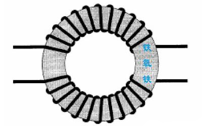
corresponding control regulations. At present, the switching frequency of switching power supplies is becoming increasingly high, and EMI is becoming increasingly serious. Therefore, EMI filters must be installed in switching power supplies. The EMI filters must suppress both normal mode and common mode noise to meet certain requirements. standard. The normal mode filter is responsible for filtering out the differential mode interference signal between the two lines at the input or output end, and the common mode filter is responsible for filtering out the common mode interference signal between the two input lines. Actual common mode inductors can be divided into three types: AC CM.M.CHOKE; DC CM.M.CHOKE and SIGNAL CM.M.CHOKE due to different working environments. They should be distinguished when designing or selecting. But its working principle is exactly the same, as shown in Figure (1):

As shown in the figure, two sets of coils with opposite directions are wound on the same magnetic ring. According to the right-hand spiral tube rule, when a differential mode voltage with opposite polarity and the same signal amplitude is applied to the input terminals A and B, When , there is a current i2 shown in the solid line, and a magnetic flux Φ2 shown in the solid line is generated in the magnetic core. As long as the two windings are completely symmetrical, the magnetic fluxes in the two different directions in the magnetic core cancel each other out. The total magnetic flux is zero, the coil inductance is almost zero, and there is no impedance effect on the normal mode signal. If a common mode signal with the same polarity and equal amplitude is applied to the input terminals A and B, there will be a current i1 shown by the dotted line, and a magnetic flux Φ1 shown by the dotted line will be generated in the magnetic core, then the magnetic flux in the core will They have the same direction and strengthen each other, so that the inductance value of each coil is twice that of when it exists alone, and XL =ωL. Therefore, the coil of this winding method has a strong suppression effect on common mode interference.
The actual EMI filter is composed of L and C. When designing, differential mode and common mode suppression circuits are often combined (as shown in Figure 2). Therefore, the design must be based on the size of the filter capacitor and the required safety regulations. Standards make decisions on inductor values.
In the figure, L1, L2, and C1 form a normal mode filter, and L3, C2, and C3 form a common mode filter.
Design of Common Mode Inductor
Before designing a common mode inductor, first check that the coil must comply with the following principles:
1 > Under normal working conditions, the magnetic core will not be saturated due to the power supply current.
2 > It must have a large enough impedance for high-frequency interference signals, a certain bandwidth, and a minimum impedance for the signal current at the operating frequency.
3 >The temperature coefficient of the inductor should be small, and the distributed capacitance should be small.
4>DC resistance should be as small as possible.
5>The induction inductance should be as large as possible, and the inductance value needs to be stable.
6 >The insulation between windings must meet safety requirements.
Common mode inductor design steps:
Step 0 SPEC acquisition: EMI allowed level, application location.
Step 1 Determine the inductance value.
Step 2 The core material and specifications are determined.
Step 3 Determine the number of winding turns and wire diameter.
Step 4 Proofing
Step 5Test
Design examples
Step 0: EMI filter circuit as shown in Figure 3
CX = 1.0 Uf Cy = 3300PF EMI level: Fcc Class B
Type: Ac Common Mode Choke
Step 1: Determine the inductance (L):
It can be seen from the circuit diagram that the common mode signal is suppressed by the common mode filter composed of L3, C2, and C3. In fact, L3, C2, and C3 form two LC series circuits, which absorb the noise of the L and N lines respectively. As long as the cut-off frequency of the filter circuit is determined and the capacitance C is known, the inductance L can be obtained by the following formula.
fo= 1/(2π√LC)L → 1/(2πfo)2C
Usually the EMI test bandwidth is as follows:
Conducted interference: 150KHZ → 30MHZ (Note: VDE standard 10KHZ – 30M)
Radiation interference: 30MHZ 1GHZ
The actual filter cannot achieve the steep impedance curve of the ideal filter, and the cutoff frequency can usually be set at around 50KHZ. Here, assuming f o = 50KHZ, then
L =1/(2πfo)2C = 1/ [( 2*3.14*50000)2 *3300*10-12] = 3.07mH
L1, L2, and C1 form a (low-pass) normal mode filter. The capacitance between lines is 1.0uF, so the normal mode inductance is:
L = 1/ [( 2*3.14*50000)2 *1*10-6] = 10.14uH
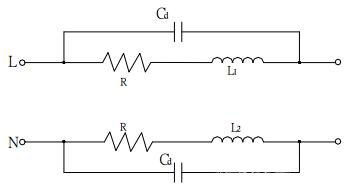
In this way, the theoretically required inductance value can be obtained. If you want to obtain a lower cut-off frequency fo, you can further increase the inductance value. The cut-off frequency is generally not less than 10KHZ. Theoretically, the higher the inductance, the better the EMI suppression effect, but an excessively high inductance will make the cutoff frequency lower, and the actual filter can only achieve a certain broadband, which makes the suppression effect of high-frequency noise worse (generally The noise component of the switching power supply is about 5~10MHZ, but there are cases where it exceeds 10MHZ). In addition, the higher the inductance, the more turns the winding has, or the higher the ui of the CORE, which will cause the low-frequency impedance to increase (the DCR becomes larger). As the number of turns increases, the distributed capacitance also increases (as shown in Figure 4), allowing all high-frequency currents to flow through this capacitance. The excessively high UI makes CORE easily saturated, and it is also extremely difficult and costly to produce.
Step 2 Determine CORE material and SIZE
From the above design requirements, we can know that the common mode inductor needs to be difficult to saturate, so it is necessary to choose a material with a low B-H angle ratio. Because a higher inductance value is required, the ui value of the magnetic core must also be high, and it must also have With lower core loss and higher Bs value, Mn-Zn ferrite material CORE is currently the most suitable CORE material that meets the above requirements.
There are no certain regulations on COEE SIZE during design. In principle, it only needs to meet the required inductance and minimize the size of the designed product within the allowable low-frequency loss range.
Therefore, CORE material and SIZE extraction should be examined based on cost, allowable loss, installation space, etc. The commonly used CORE value of common mode inductors is between 2000 and 10000. Iron Powder Core also has low iron loss, high Bs and low B-H angle ratio, but its ui is low, so it is generally not used in common mode inductors, but this type of core is one of the normal mode inductors. Preferred materials.
Step 3 Determine the number of turns N and wire diameter dw
First determine the specifications of the CORE. For example, in this example, T18*10*7, A10, AL = 8230±30%, then:
N = √L / AL = √(3.07*106 ) / (8230*70%) = 23 TS
The wire diameter is based on the current density of 3 ~ 5A/mm2. If space allows, the current density can be selected as low as possible. Assume that the input current I i = 1.2A in this example, take J = 4 A/mm2
Then Aw = 1.2 / 4 = 0.3 mm2 Φ0.70 mm
The actual common mode inductor must be tested through actual samples to confirm the reliability of the design, because differences in manufacturing processes will also lead to differences in inductor parameters and affect the filtering effect. For example, an increase in distributed capacitance will cause high-frequency noise. Easier to transmit. The asymmetry of the two windings makes the difference in inductance between the two groups larger, forming a certain impedance to the normal mode signal.
Summarize
1 >The function of the common mode inductor is to filter out the common mode noise in the line. The design requires that the two windings have a completely symmetrical structure and the same electrical parameters.
2 >The distributed capacitance of the common mode inductor has a negative impact on suppressing high-frequency noise and should be minimized.
3 >The inductance value of the common mode inductor is related to the noise frequency band that needs to be filtered and the matching capacitance. The inductance value is usually between 2mH ~50 mH.
Article source: Reprinted from the Internet
Xuange was established in 2009. The high and low frequency transformers, inductors and LED drive power supplies produced are widely used in consumer power supplies, industrial power supplies, new energy power supplies, LED power supplies and other industries.
Xuange Electronics enjoys a good reputation in domestic and foreign markets, and we accept OEM and ODM orders. Whether you choose a standard product from our catalog or seek help with customization, please feel free to discuss your purchasing needs with Xuange.
https://www.xgelectronics.com/products/
William (General Sales Manager)
186 8873 0868 (Whats app/We-Chat)
E-Mail: sales@xuangedz.com
liwei202305@gmail.com
(Sales Manager)
186 6585 0415 (Whats app/We-Chat)
E-Mail: sales01@xuangedz.com
(Marketing Manager)
153 6133 2249 (Whats app/We-Chat)
E-Mail: sales02@xuangedz.com
Post time: May-28-2024