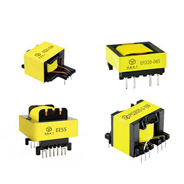
The high-frequency transformer is one of the core components of the switching power supply. It has three functions: energy transmission, voltage conversion and electrical isolation. The operating frequency of the high-frequency transformer is usually 20~100kHz. Compared with the industrial frequency transformer (also called power transformer) working at 50/60Hz, the high-frequency transformer has the remarkable characteristics of small size, light weight and high efficiency, which is also the fundamental reason why the switching power supply can be miniaturized.
There are two energy transmission modes for the high-frequency transformer in the switching power supply: one is the transformer transmission mode, and the other is the inductor transmission mode. The transformer transmission mode is the same as the principle of the ordinary industrial frequency transformer. A certain voltage is applied to the primary winding to produce a magnetic flux change in the transformer core, so that the secondary winding induces a voltage and transmits the electric energy from the primary to the secondary of the transformer; the inductor transmission mode uses the inductor energy storage principle. A voltage is applied to the primary winding for a certain period of time to generate an excitation current to magnetize the transformer core, converting the electric energy into magnetic energy and storing it in the transformer core. When the excitation current is interrupted, the electromagnetic induction phenomenon causes the secondary winding to generate a current, converting the magnetic energy in the transformer core into electric energy and transmitting it to the secondary. High-frequency transformers are composed of magnetic cores, skeletons, coils and insulating tapes.
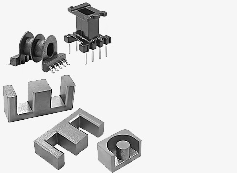
The core material of high-frequency transformers has a great influence on their performance and cost. The core of high-frequency transformers in switching power supplies is generally a soft magnetic material used in low magnetic fields, which should have the characteristics of high magnetic permeability, low coercivity and high resistivity. Magnetic materials commonly used in high-frequency transformers include soft ferrites, Permalloy and non-ferrous alloys. Among the many magnetic materials, almost every core material can be used in switching power supplies, but no material has these three characteristics at the same time, and some materials are expensive.
Taking all factors into consideration, power iron body materials are a better choice in the operating frequency range of 50~100kHz, and are most widely used in switching power supplies. Power ferrite is a kind of soft ferrite, which has a saturation magnetic induction intensity of 0.4~0.5T, excellent low loss/frequency relationship and low loss/temperature relationship. In other words, as the frequency increases, the loss does not increase much; as the temperature increases, the loss does not change much. Widely used in power chokes (also called power inductors), filters, switching power supply high-frequency transformers and power factor correction circuits.
The energy transmission method of high-frequency transformers is related to the topological structure of the switching power supply. The high-frequency transformers of forward, push-pull, half-bridge/full-bridge switching power supplies all adopt transformer transmission, and only the high-frequency transformer of flyback switching power supplies adopts inductor transmission. The design requirements and related calculation formulas of the two methods are quite different, but in the design of high-frequency transformers, the basic methods of core materials and parameter selection are the same.
Filter inductors are used in buck/boost DC/DC converters, forward, push-pull, half-bridge/full-bridge topological switching power supplies. These inductors usually flow through large DC currents, so they are called power inductors, or power inductors for short. Power inductors can be made with power ferrite cores or several powder cores. When winding power inductors on the core of a high-frequency transformer using ferrite materials, a large air gap must be added to prevent magnetic saturation of the core.
The more commonly used magnetic core material for winding power inductors is powder core magnetic material, referred to as magnetic powder core. Powder core magnetic materials are usually made into a ring shape, referred to as magnetic ring. The magnetic powder cores used in power inductors mainly include iron powder core (Iron Powder in English), sendust core (Sendust Core in English) and iron nickel molybdenum powder core (also known as molybdenum permalloy powder core, MPFCore in English). Iron powder core (lron) is usually composed of carbon-based ferromagnetic powder and resin carbon-based ferromagnetic powder, and has the lowest price among powder cores. Its saturation flux density (also known as saturation magnetic induction intensity) value is about 1.0T, and the effective magnetic permeability (referred to as magnetic permeability) ranges from 22 to 100. The initial magnetic permeability has good stability with frequency changes and good DC current superposition performance. However, its magnetic core loss is large when working at high frequencies, and it is usually used in the output filter circuit of switching power supplies and DC/DC converters below 50kHz. Sendust powder core is composed of 85% Fe, 9% Si and 6% Al powder. It is mainly used to replace iron powder core. Its loss is 80% lower than that of iron powder core. It can be used at frequencies above 50kHz. The saturation flux density is about 1.05T, the magnetic permeability is 26~125, the magnetostriction coefficient is close to zero, and no noise is generated when working at different frequencies. It has better DC bias characteristics than iron nickel molybdenum powder core (MPP) and has the best performance-price ratio.
Sendust powder core is mainly used in circuits such as AC inductance, output inductance, line filter, power factor correction, etc., and sometimes it is also used as a high-frequency transformer core instead of air-gap ferrite. Iron nickel molybdenum powder core (MPP) is composed of 17% Fe, 81% Ni and 2% Mo powder. The main features are saturation flux density value of about 7500Gs, magnetic permeability range of up to 14~350, the lowest loss in powder core, excellent temperature stability, and widely used in space equipment, open-air equipment, etc. Its magnetostriction coefficient is close to zero, and it is silent when working at different frequencies. It is mainly used in high-quality factor (Q) filters below 300kHz, inductive load coils, 1C circuits with high temperature stability requirements for vibration circuits, output inductors, power factor compensation circuits, etc. But its price is also the most expensive. When selecting the core material of the power inductor, the iron powder core should be considered first, so that the cost of the inductor can be minimized.
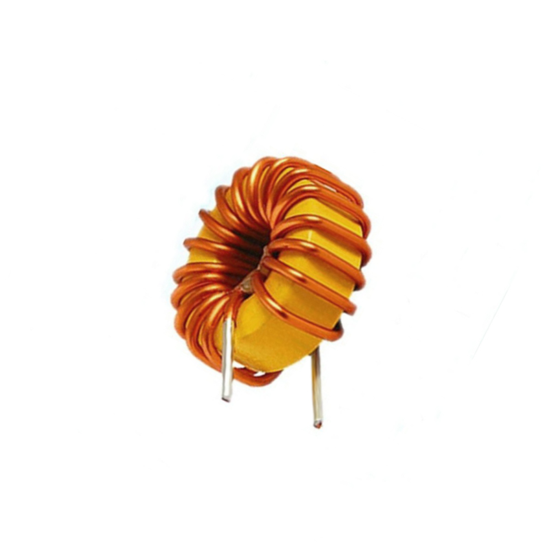
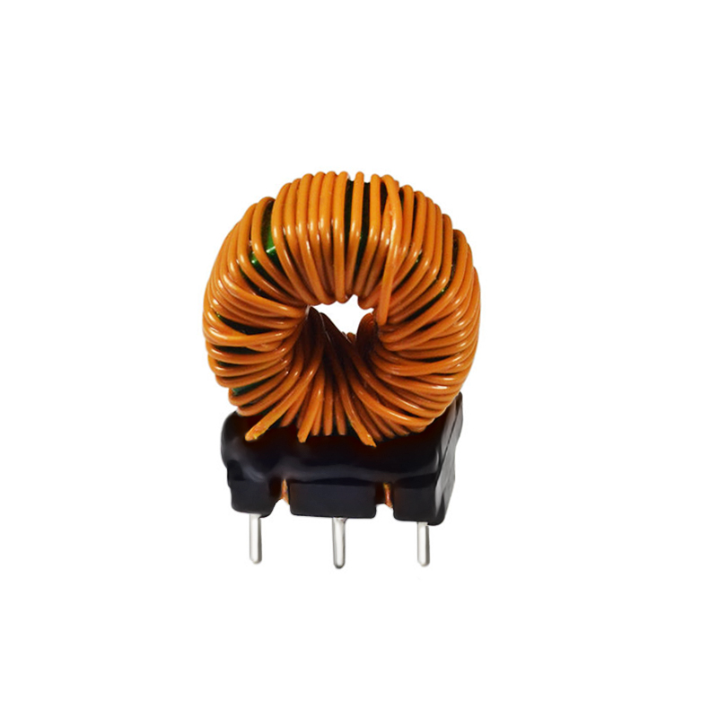
(a) (b) (c)
When the iron powder core cannot meet the design requirements, the iron silicon aluminum powder core can be selected to obtain a better performance-price ratio. Only when the inductor size and loss requirements are very stringent, it is necessary to choose the iron nickel molybdenum powder core. The figure shows the appearance of several power inductors. Figure (a) shows a magnetic ring inductor wound with a toroidal magnetic core, which is usually used in switching power supplies with large output current. The magnetic ring material is usually iron powder core, iron silicon aluminum powder core or iron nickel molybdenum powder core. Figure (b) shows a magnetic ring inductor wound with an I-shaped magnetic core, which is usually used in switching power supplies with small output current. The I-shaped core is usually made of power ferrite material; Figure (c) shows a magnetic ring inductor with a fixed base, but a fixed base is installed on the inductor shown in Figure (a) to improve the vibration and impact resistance of the inductor.
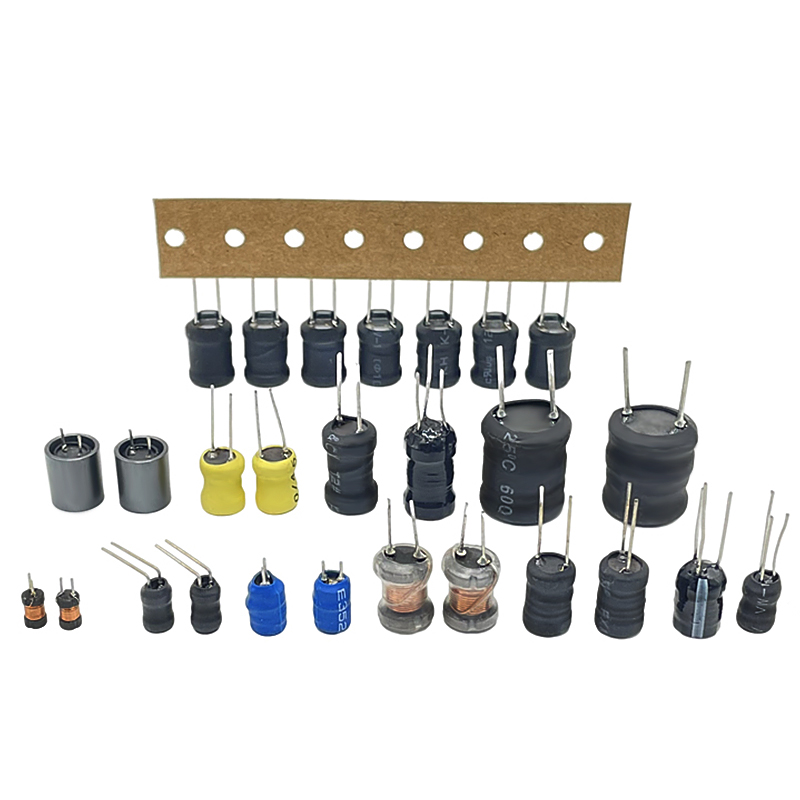
In addition, with the miniaturization of electronic products and the development of SMT technology, the application of chip inductors in switching power supplies is becoming more and more widespread. The figure shows the appearance of several chip power inductors. Chip inductors are generally made of power ferrite cores, and have two structures: dispersed and closed. The open structure uses an I-shaped core, whose inductor coil is exposed to the air and has a large leakage inductance; the closed structure uses a pot-shaped core, whose inductor coil is enclosed inside the core and has a small leakage inductance. The pot-shaped core also leaves enough air gap (referred to as air gap) to prevent the core from producing magnetic saturation.
Special note: The color-coded inductor (also called color ring inductor) in general electronic circuits is designed for small signal circuits and is wound with very fine enameled wire, which can only pass a few or tens of milliamperes (mA). The power inductor has a larger core. It is wound with thicker enameled wire and can withstand currents of hundreds of milliamperes (mA), several amperes (A), or even tens of amperes (A). Therefore, the color-coded inductor must not be used to replace the power inductor. Note: The power inductor cannot be replaced by an ordinary color-coded inductor.
XuanGe Electronic Components Manufacturer
☆Welcome to contact us, free samples
▷Whats app / We-Chat: 18688730868
▷E-Mail: sales@xuangedz.com
Articles you may be interested in:
▷The difference between switching power supply and linear power supply
▷Detailed explanation of transformer high voltage failure caused by skeleton
▷What are the main factors causing abnormal noise in high-frequency transformers?
▷The heart of the switching power supply module – switching transformer
Post time: Feb-25-2025