This article will focus on the detailed description of the test methods of low-frequency transformers and high-frequency transformers, hoping to be helpful to you.
Low-frequency transformer
Low-frequency transformers are used to transmit signal voltage and signal power, and can also achieve impedance matching between circuits, and have an isolation effect on DC. There is no difference in principle between high-frequency transformers and low-frequency transformers. However, due to the different frequencies of high frequency and low frequency, the iron cores used in transformers are different. Low-frequency transformers generally use silicon steel sheets with high magnetic permeability, while high-frequency transformers use high-frequency ferrite cores.
Working principle
Tongue mouth 32 mm, thickness 34 mm, width 96 mm, maximum power use how thick the wire, tongue mouth refers to, EI type transformer core cross-sectional area refers to the width of the middle horizontal line of the E sheet (inserted into the middle square mouth of the Satons transformer bobbin), that is, the product of the core tongue width and the total thickness of all E sheets inserted into the square mouth of the transformer bobbin, that is, the stack thickness. The simplest is to refer to the area of the middle square mouth of the transformer bobbin. The transformer core cross-sectional area refers to the part covered by the coil: tongue width x stack thickness = cross-sectional area, unit: cm2.
The first calculation method
(1) Transformer silicon steel sheet cross section: 3.2 cm*3.4 cm*0.9=9.792 cm2
(2) Calculate transformer power based on silicon steel sheet cross section: P=S/K^2= (9.79/1.25)^2=61.34 watts (take 60 watts)
(3) Calculate the number of turns per volt of the coil based on the cross section: W=4.5*105/BmS=4.5*105/(10000*9.79) =4.6 turns/volt
(4) Number of turns of the primary coil: 220*4.6=1012 turns
(5) Current of the primary coil: 60W/220V=0.273A
(6) Wire diameter of the primary coil: d=0.715 =0.37(mm)
(7) Number of turns of the secondary coil: 2*(51*4.6*1.03) =2*242 (turns) (1.03 is the voltage reduction factor, two-stage 51V=2*242 turns)
(8) Secondary coil current: 60W/(2*51V) =0.59A
(9) Secondary wire diameter: d=0.715=0.55 (mm)
The second calculation method
The tongue width of the E-shaped iron core is calculated based on the middle tongue. Calculation formula: Output power: P2=UI
Taking into account the loss of the transformer, the primary power: P1=P2/n (where n=0.7~0.9, generally the larger value is chosen for the larger power)
The calculation formula for the number of turns per volt: N (number of turns per volt) = 4.5×10⁵/BxS (B=magnetic permeability of silicon steel sheet, generally 8000~12000 Gauss, a large value is chosen for a good silicon steel sheet, otherwise a small value is chosen. S=area of the iron core tongue, in cm2) If the quality of the silicon steel sheet can generally be selected as 10000 Gauss, then it can be simplified to:
N=45/S
When calculating the number of turns of the secondary winding, considering the transformer leakage inductance and the copper loss of the wire, a 5% winding margin must be added. No margin is needed for the primary.
Calculate the wire diameter from the current: I=P/U (l=A, P=W, U=V)
Select with wire diameter per square millimeter ≈ 2.5~2.6A.
The third calculation method
First of all, it should be noted that the cross-sectional area of the transformer is the cross-sectional area of the coil. If your core area (coil area) is 32*34=1088m㎡=10.88 c㎡
Simple calculation of small transformers:
1. Calculate the number of turns per volt
The number of turns per volt = 55/core cross section
For example, your core cross section = 3.5×1.6=5.6 square centimeters
Therefore, the number of turns per volt = 55/5.6=9.8 turns
2. Calculate the number of turns of the coil
Primary coil n1=220×9.8=2156 turns
Secondary coil n2=8×9.8×1.05=82.32, which can be taken as 82 turns
The 1.05 in the calculation of the number of turns of the secondary coil is to consider the voltage drop when there is a load
3. Find the wire diameter
You did not specify how many volts and currents you want to output? Here I assume 8V and 2A.
Transformer output capacity = 8X2 = 16 volt-amperes
Transformer input capacity = transformer output capacity/0.8 = 20 volt-amperes
Primary coil current I1 = 20/220 = 0.09 amperes
Wire diameter d = 0.8√1
Primary coil wire diameter d1 = 0.8√I1 = 0.8v0.09 = 0.24 mm
Secondary coil wire diameter d2 = 0.8√I2 = 0.8√2 = 1.13 mm
Pay attention to the insulation of interlayer voltage and lead-out insulation.
What is the impact of using a high-frequency transformer in a low-frequency circuit?
When a high-frequency transformer is used in a low-frequency circuit, the current increases and the transformer may be burned out. Because the inductance is proportional to the frequency of the alternating current.
When a low-frequency transformer is used in a high-frequency circuit, the current decreases. Because the inductance is proportional to the frequency of the alternating current, the transformer will not be damaged. The high-frequency circuit cannot work properly.
High-frequency transformer refers specifically to switching power transformer, not industrial frequency transformer (50~60Hz operating frequency). Switching power transformer usually operates at 20K~200K HZ range, and its inductance is also very small, between 100 microhenry and 1 millihenry.
The inductance of industrial frequency transformer is at least Henry (1000uH microhenry = 1mH millihenry; 1000mH millihenry = 1H Henry;) level or above.
According to the impedance principle, under the same inductance and the same voltage, the higher the operating frequency, the greater the inductance and the smaller the current; the lower the frequency, the smaller the inductance and the current becomes very large and close to short circuit.
Secondly, the magnetic core of the switching power transformer is also different, it is ferrite; while the industrial frequency transformer is iron silicon sheet, which is composed of many iron silicon sheets stacked together, in order to improve work efficiency and reduce magnetic loss eddy current.
1.High-frequency transformer test method
Generally speaking, the items required to be tested for high-frequency transformers are:
1. Inductance
2. Leakage inductance
3. Withstand voltage
4. Insulation resistance
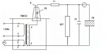
2. Inductance and inductance test method
Concept: The primary inductance of the transformer refers to the effective inductance of the primary winding when the secondary is open.
Test conditions: The test conditions of the transformer are consistent with its working conditions. Due to the nonlinearity of the transformer core magnetization curve, when the frequency, AC voltage, and DC magnetizing current change, the effective magnetic permeability of the core also changes, causing the inductance to change.
Test conditions that must be specified for testing inductance:
1. Test frequency;
2. AC voltage across the transformer or inductor;
3. DC magnetizing current.
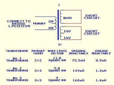
3. Leakage inductance and leakage inductance test method
Concept: Leakage inductance refers to the inductance generated by the leakage flux that does not interlink between coils. It is related to factors such as coil size, winding arrangement, and number of turns. Leakage inductance is a linear inductance and has nothing to do with the test voltage.
Classification of leakage inductance:
1. Primary leakage inductance. Refers to the inductance measured at the primary when all secondary windings are short-circuited.
2. Secondary leakage inductance. Refers to the inductance measured at the secondary when the primary winding of the transformer is short-circuited.
3. Leakage inductance of the primary to any secondary winding. For transformers with several windings (such as multi-impedance output transformers), the inductance measured at the primary when half of the primary is short-circuited.
4. Safety test
Insulation resistance. The insulation resistance of each winding of the transformer and between the winding and the iron core and the electrostatic shielding layer should be greater than 1000MΩ under normal conditions, and should not be less than 10MΩ after high temperature test and constant temperature test (IEC-65 stipulates that it should not be less than 4MΩ). The DC voltage for testing insulation resistance is 500V.
5. Withstand voltage test
The transformer primary and secondary windings, iron core, and electrostatic shielding layer should be able to withstand 50Hz, 3500V (effective value) voltage (IEC-65 stipulates that it is 3000V effective value). The secondary winding and the iron core and electrostatic shielding layer can withstand 50Hz, 1000V (effective value) voltage without breakdown and arcing. The current is limited to 1mA (this value depends on the transformer power, and the maximum does not exceed 10mA.
6. Output wiring technology
When the high-frequency transformer (such as FLYBACK) supplies energy to the load system, if the lead is long and the wiring is unreasonable, the parasitic capacitance generated between the lines will increase to a level that cannot be ignored, and the common-mode noise will be transmitted and introduced into the load system through this parasitic capacitance, making the load system unable to work normally.
Experiments have shown that the use of cross-wires is better than parallel wires for transmission, that is, the two wires at the output end are directly cross-wired together, and then transmitted to the load through the filter capacitor, which can achieve a good filtering effect. This method is the most economical, effective, and most commonly used in practical applications.
7. Shielding and shielding technology
Purpose: To eliminate the electrical coupling between windings through distributed capacitance, and to prevent external high-frequency signals from interfering with the transformer’s working signals and loads.
Measures: Electrostatic shielding, core grounding, metal cover on transformer.
Method: For electrostatic shielding, use copper tape or metal insulation film to isolate and surround the primary and secondary to form an electrical shield. The shield thickness must be much smaller than the penetration depth, generally one-third of the penetration depth. The shield should be directly welded to the “static” (input power + or -) voltage terminal or the ground of the primary coil of the transformer with the minimum lead inductance, and the shield itself should not be insulated to form a short-circuit turn, so that it can play a shielding role.
8. Leakage inductance and the influence of leakage inductance
Generally speaking, the primary of the transformer has more or less leakage inductance, and some high-frequency transformers are used in switching power supplies (switching). The switching power supply uses an IC, generally called a power switch tube. When the power switch tube is turned from on to off, a back electromotive force is generated, and the back electromotive force will charge and discharge the distributed capacitance of the primary coil of the transformer, thereby generating damped oscillation, that is, ringing. The amplitude of the electromotive force generated by the leakage inductance is also very high, and its energy is also very large, so the loss of the drain clamp circuit is large and the efficiency of the power supply is low. If no protective measures are taken, the damped oscillation generated by the back electromotive force will also generate strong electromagnetic radiation, which will not only cause serious interference to the machine itself, but also to the surrounding environment of the machine.
For a high-frequency transformer that meets international standards for insulation and safety, its leakage inductance should be 1%~3% of the primary inductance when the secondary is open.
9. Measures to reduce leakage inductance
In order to reduce the impact of electromagnetic induction caused by the leakage inductance of the transformer on the surrounding circuit, on the one hand, the leakage inductance of the transformer must be small, and on the other hand, a thin layer of copper foil must be wrapped around the outer periphery of the transformer to form a low-impedance short-circuit coil to dissipate the inductive energy generated by the leakage inductance through eddy current.
How to minimize the leakage inductance of the transformer?
1. Reduce the number of turns of the winding and select magnetic materials with high saturation magnetic induction intensity and low loss.
2. Reduce the thickness of the winding and increase the height of the winding;
3. Reduce the insulation thickness between windings as much as possible;
4. Use layered cross winding for the primary and secondary windings;
5. For toroidal core transformers, they should be wound evenly around the toroidal core.
10. The influence of distributed capacitance and reduction measures
The influence of distributed capacitance: Distributed capacitance is the channel that causes common mode noise between the primary and secondary of the switch. It not only reduces the efficiency of the switching power supply, but also forms an LC oscillator with the distributed inductance of the winding, generating ringing noise, among which the influence of the distributed capacitance of the primary winding is particularly significant.
Methods to reduce distributed capacitance:
1. Minimize the length of each turn of wire;
2. Add an insulation layer between the primary windings.
11. Loss of high-frequency transformer
A high-efficiency high-frequency transformer should have the following conditions: low DC loss and AC loss, small distributed capacitance of the winding itself and coupling capacitance between windings.
Transformer loss:
1. DC loss. It is caused by the copper loss of the coil. To improve efficiency, thicker wires should be selected as much as possible, and the current density should be within the range of 4~10A/MM2.
2. AC loss. It is caused by the skin effect of high-frequency current and the core loss. The phenomenon that high-frequency current always tends to flow through the surface of the wire when passing through the wire is called the skin effect.
The loss of the transformer is the sum of the two.
12. Classification of core loss
The total loss of soft ferrite core is usually divided into three types: hysteresis loss, eddy current loss Pc and residual loss Pr.
Hysteresis loss is proportional to the area of the DC hysteresis loop and is linearly related to frequency.
Eddy current loss Pc=Cef2B2/p, where Ce is the size constant and p is the resistivity at the anchor point measurement frequency f. As the frequency increases, the proportion of eddy current loss in the total loss gradually increases. When the operating frequency reaches 200~500kHZ, eddy current loss has become dominant.
13. Introduction to eddy current loss
When an AC voltage is applied to the core coil, the excitation current flows through the coil, and all the magnetic flux Φ generated by the excitation ampere-turn passes through the core. If the core is a conductor, all the magnetic flux will be linked around the cross section of the core itself to form a single-turn secondary coil.
When the AC excitation voltage is U1, according to the law of electromagnetic induction, U1= N1dΦ /d t, the induced potential of each turn, that is, the induced potential equivalent to one turn of the maximum periphery of the core cross section is U1/N1=dФ /d t.
Because the resistivity of the core material is not infinite, there is a certain resistance value along the periphery of the core, and the induced voltage generates a current ie, that is, eddy current, which flows through this resistance and causes loss, that is, eddy current loss.
14. The role and method of the core air gap
The role of the air gap:
1. Avoid core saturation, reduce the residual magnetic induction intensity, and increase the DC magnetic field intensity of the core.
2. Make the magnetization curve tilt to increase the DC working magnetic field.
The air gap is best opened in the middle column. Because the stray magnetic flux, edge magnetic flux and end magnetic flux all pass through the cross section of the coil center, the magnetic flux density here is the largest, and saturation may occur first.
15. Two important concepts
Skin effect. When alternating current passes through the wire, the current on the wire cross section is unevenly distributed due to the different magnetic fluxes interlinked by the inner and edge parts of the wire, which is equivalent to a reduction in the effective area of the wire. This phenomenon is called the skin effect. As the operating frequency increases, the skin effect has a greater impact.
Penetration depth. The penetration depth is the radial depth that the alternating current can reach along the surface of the wire due to the skin effect. When the wire flows through a high-frequency alternating current, the reduction in the effective cross section can be expressed by the penetration depth.
Principles of wire selection. When selecting the wire diameter of the primary and secondary of the transformer, the principle that the wire diameter should be less than twice the penetration depth should be followed. When the required wire diameter is greater than the wire diameter determined by twice the penetration depth, a small diameter wire (the diameter should be less than twice the penetration depth) can be used to wind multiple strands or a flat copper wire design can be used.
Other articles you may be interested in:
▶ How to detect the core of a high frequency transformer?
▶ Leakage sensing and temperature rise of high frequency transformer
▶ Why does the high-frequency transformer keep squeaking? How to solve this problem?
XuanGe Electronics
15 years of professional production of high-frequency transformers, low-frequency transformers, potting transformers, inductors, filters and other products.
Can design, sample and produce according to the parameters provided by customers.
Post time: Oct-18-2024