This article mainly introduces the whole process of Flyback transformer design. Let’s study it carefully!
1. Input conditions
Maximum input voltage Vinmax: 310V
Minimum input voltage Vinmin: 110V
First output voltage Vo1: 5V
First output diode voltage drop VD1: 0.7V
First output current Io1: 0.5A
Second output voltage Vo2: 12V
Second output diode voltage drop VD2: 0.7V
Second output current Io2: 5A
Switching frequency fs: 70kHz
Efficiency n: 0.88
Output current ripple Krp[1]: 0.4
Maximum duty cycle Dmax[2]: 0.45
Fill factor Ku: 0.2
Maximum magnetic flux density Bmax: 0.3T
Current density J: 6A/mm^2
[1] This value is for CCM mode. If Flyback works completely in DCM mode, Krp=1.
[2] Why can the duty cycle of Buck, Boost and Buck-Boost inductors be calculated directly, while the Flyback needs to be determined in advance? According to the working principle of Flyback, Vo/Vin=(Ns/Np)*D(1-D).
If the turns ratio is unknown, the duty cycle needs to be determined first. In fact, in the design process, fractional turns often involve rounding, which leads to changes in the turns ratio, and the changes in the turns ratio will affect the maximum duty cycle. Therefore, the design of the Flyback transformer sometimes requires iteration. As for why the maximum duty cycle is pre-set to 0.45? This will be discussed later.
2. Calculation process
1. Calculate the peak current and the effective value of the primary and secondary currents
Before the calculation, let me explain why we need to calculate the peak current and the effective value of the current. The peak current corresponds to the maximum value of the magnetic flux density, which determines whether the magnetic core is saturated; the effective value of the current is used to roughly estimate the wire gauge and determine the wire diameter of the conductor. Here, we also deduce the current waveform in the primary and secondary windings. On the one hand, it is more convenient to use the software to calculate the effective value, and on the other hand, when optimizing the winding design in the future, it is necessary to perform Fourier decomposition on the winding current waveform. Otherwise, it is very frustrating to calculate without knowing why.
a. Input average current
ldc=(Vo1*lo1+Vo2*Io2)/(η*Vinmin)
ldc=0.625A
b. Peak current calculation
(1) Primary current peak and current waveform
The primary current waveform and function of the Flyback transformer are as follows,
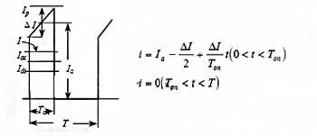
Figure 1 Flyback transformer primary current waveform and function relationship
In Figure 1, the average value of the primary current is 1dc, and the center value of the trapezoidal wave current is la. The relationship between the two is as follows:
The center value of the primary trapezoidal wave can be calculated from the above formula,
la=ldc/Dmax=1.389A
The primary current ripple coefficient is the same as before,
△l=Krp*la=0.556A
The relationship between the center value of the primary trapezoidal wave and the primary peak current,
lpk=la+4l/2=1.514A
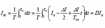
Substituting the center value of the trapezoidal wave, ripple current, maximum duty cycle and frequency into the function in Figure 1, the primary current waveform can be obtained.
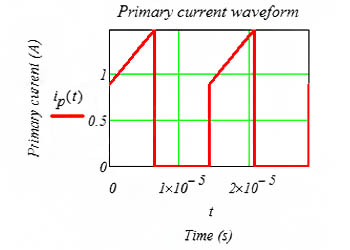
Figure 2 Flyback transformer primary Np current waveform
(2) Secondary current peak and current waveform
The derivation of the secondary current waveform is similar to the primary current waveform. The difference is that in 0~Ton, the secondary current is zero; in Ton~T, the secondary current decreases linearly.
The average value of secondary 1 current is:
ldc_s1=lo1=0.5A
The center value of the secondary 1 trapezoidal wave:
la_s1=ldc_s1/(1-Dmax)=0.182A
The secondary 1 current ripple coefficient is the same as before,
△l_s1=Krp*Ia_s1=0.073A
The relationship between the center value of the secondary 1 trapezoidal wave and the secondary 1 peak current,
lpk_s1=la_s1+4I_s1/2=0.219A
The current waveform of secondary side 1 can be determined by (Ton, lpk_s1) and (T, Ipk_s1-4l_s1).
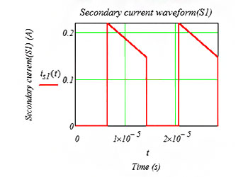
Figure 3 Flyback transformer secondary side Ns1 current waveform
Similarly, the relevant current of secondary side 2 can be calculated.
The average current of secondary side 2 is:
ldc_s2=lo2=5A
The center value of the trapezoidal wave of secondary side 2:
la_s2=ldc_s2/(1-Dmax)=9.091A
The current ripple coefficient of secondary side 2 is the same as before,
△l_s2=Krp*la_s2=3.636A
The relationship between the center value of the trapezoidal wave of secondary side 2 and the peak current of secondary side 2,
lpk_s2=la_s2+4l_s2/2=12.727A
The current waveform of secondary side 2 can be determined by (Ton,lpk_s2) and (T,Ipk_s2-4l_s2).
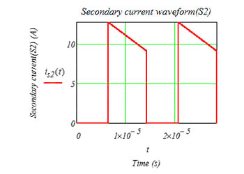
Figure 4 Flyback transformer secondary side Ns2 current waveform
C. Current effective value calculation
In fact, the original secondary side current effective value can be directly integrated and calculated in MathCAD, so there is no need to pay attention to the calculation details in the middle. Of course, the calculation formula of the current effective value is also explained in detail below.
According to the definition of effective value,
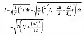
Substituting Dmax, la and △l into the above formula, we can get the effective value of the primary current
lprms=0.932A
Similarly, we can get the effective value of the secondary current
ls1rms=0.135A
ls2rms=6.742A
2. Calculate the inductance
Inductance:
L=(Vinmin*Dmax)/(f*AI)
L=1272uH
3. Calculate the AC magnetic flux density
Inductance:
Bac=((AI/2)/Ipk)*Bmax
Bac=0.055T
4. Select the core by AP method
AP value:
AP_cal=[(1+η)*Vinmin*lprms*Dmax]/(Ku*Jc*f*2Bac)
AP_cal=9376mm^4
Core selection: PQ2625
Core effective cross-sectional area:
Ae=120mm^2
Core window area:
Aw=84.5mm^2
Core effective magnetic path length:
le=55.5mm
Core volume:
Ve=6530mm^3
Core AP value:
AP_core=10140mm^4
5. Transformer ratio
Transformer ratio theoretical value Np:Ns1:
n_cal=(Vinmin*Dmax)/((Vo1+VD1)*(1-Dmax))
n_cal=15.79
Transformer ratio theoretical value Np:Ns2:
n_cal=(Vinmin*Dmax)/((Vo2+VD1)*(1-Dmax))
n_cal=7.09
The ratio calculated here is only a theoretical value, and there is no need to consider the number of turns of the primary and secondary sides under this ratio. Because rounding is involved in the calculation of the number of winding turns, the ratio will be slightly adjusted.
6. Turns calculation
Calculation of primary turns:
Np_cal=(Vinmin*Dmax)/(fs*2Bac*Ae)
Np_cal=53.53
Calculation of secondary turns 1:
Ns1_cal=((Vs1+VD1)*(1-Dmax))/(fs*Ae*2Bac)
Ns1_cal=3.39
Ns1=3 after rounding
Calculation of secondary turns 2:
Ns2_cal=((Vo2+VD2)*Ns1)/(Vo1+VD1)
Ns2_cal=6.68
Ns2=7 after rounding
After rounding the secondary turns, recalculate the primary turns
Np_cal=Ns1_actual value*n
Np=47.37
After rounding, Np=47
7. Maximum duty cycle calculation
At the beginning of the design, a maximum duty cycle is set first, and then other parameters such as the turns ratio are determined. There will be rounding in the process of turns calculation, so the turns ratio will be adjusted, so the actual maximum duty cycle of the designed transformer will be calculated here.
The real turns ratio Np: Ns1
n=Np/Ns1
n=15.67
The actual maximum duty cycle:
Dmax=(n*Vo1)/(n*Vo1+Vin)
Dmax=0.416
The maximum duty cycle for a specific core, a specific number of winding turns, and a specific input and output condition has been determined. Then there is a problem, that is, the previous calculations are based on the preset maximum duty cycle. In fact, this does not affect the design of the transformer. You only need to iterate the current and inductance once.
8. Maximum flux density calculation
According to Faraday’s law of induction, the change of the maximum duty cycle will affect the change of the AC flux density, thereby affecting the change of the maximum flux density. Therefore, when the core, number of turns, and maximum duty cycle are determined, it is necessary to confirm the maximum flux density again to ensure that the core will not saturate.
AC flux density calculation:
Bac=(Vinmin*Dmax)/(f*2Np*Ae)
Bac=0.058T
Maximum flux density calculation:
Bmax=Bac/((△I/2)/Ipk)
Bmax=0.316T
Next, you need to confirm the wire gauge, fill factor and air gap. This is the same as the previous calculation method, so I will not explain it in detail.
3. Output results
Core size: PQ2625
Core material: DMR95 or equivalent
Primary winding turns: 47
Secondary 1 winding turns: 3
Secondary 2 winding turns: 7
Inductance: 1272uH
Maximum magnetic flux density: 0.316T
Flyback converters are often used in auxiliary power supplies, and transformers generally have multiple winding outputs, and multiple winding outputs will have cross-regulation issues. Next time, I will talk about the cross-regulation issue.
XuanGe Electronics
The article comes from the Internet, and all the reprinted content belongs to the original author
Post time: Oct-22-2024