As we all know, the transformer is a static electrical equipment used to transform AC voltage and current and transmit AC power. However, the traditional transformer and the high power density transformer are different, because the content is too much, this paper only describes the winding structure part of the difference.
A. the traditional transformer
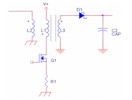
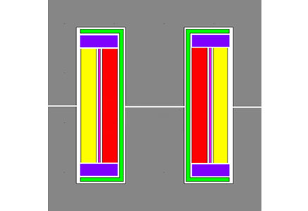
Single output Flyback and common transformer winding structure
Red: primary winding
Purple: auxiliary winding
Yellow: secondary winding
Features: The auxiliary winding is sandwiched between the primary and secondary
Cons:
(1) The proximity effect is strong, and the winding AC loss is large
(2) The leakage between the primary and secondary is large, the absorption loop loss is large, and the efficiency is low.
Advantages:
(1) The process structure is very simple and easy to manufacture
(2) The primary outer layer is connected to the V+ end of the potential static, which is easy to achieve no Y.
Improved Flyback transformer winding structure (simple type)
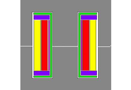
Red: primary winding
Purple: auxiliary winding
Yellow: secondary winding
Features: The auxiliary winding is located in the innermost layer of the wire package, the primary is in the middle and the secondary is outside.
Disadvantages: The proximity effect is strong, and the winding AC loss is large.
Advantages:
(1) The process structure is very simple and easy to manufacture
(2) The primary outer layer is connected to the V+ end of the potential static, which is easy to achieve no Y
(3) The leakage between the primary stages is small, the absorption loop loss is small, and the efficiency is high.
Improved Flyback transformer winding structure (Sandwich type)
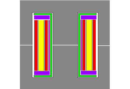
Red: primary winding
Purple: auxiliary winding
Yellow: secondary winding
Features: The auxiliary winding is located in the innermost layer of the wire package, and then the primary half, the secondary all, and the other half of the primary;
Cons:
1, the secondary proximity effect is strong, and the winding AC loss is large
2, the primary half of the winding does not have any electrostatic potential layer for shielding, can not achieve no Y
Advantages:
(1) The complex process structure is not conducive to manufacturing;
(2) The leakage between the primary stages is small, the absorption loop loss is small, and the efficiency is high
(3) The primary proximity effect is small, and the winding AC loss is small
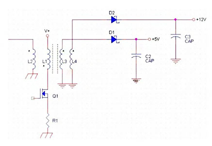
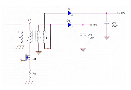
Flyback multiplex output
Leakage between L3 and L4, causing cross adjustment.
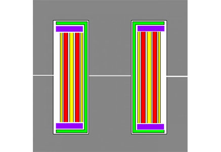
Practical multiplex output type
The high-voltage output winding is superimposed on the low-voltage winding, double-wire and wound to reduce the cross adjustment.
Power transmission transformer (including forward drive, push pull, half bridge, full bridge)
Reasonable winding structure, layer thickness less than 2△
Red: primary winding
Purple: auxiliary winding
Yellow: secondary winding
A model of the actual transformer
Inside the dotted line is the ideal transformer
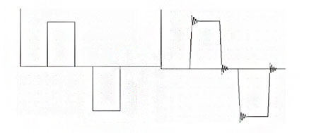
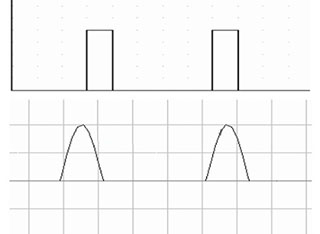
Pulse transformer signal transmission distortion
Due to the leakage of the primary side and the amplitude side and the existence of the resistance component, the pulse will produce delay, slope slowing, ringing and top drop after passing through the transformer.
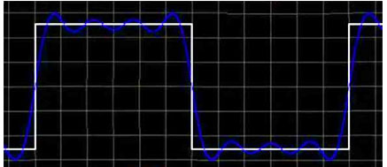
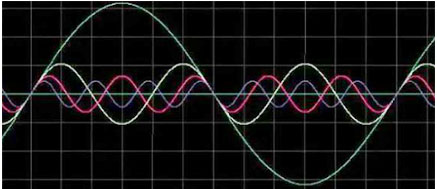
Decomposition of pulse current
The pulse current consists of fundamental current and each higher harmonic current
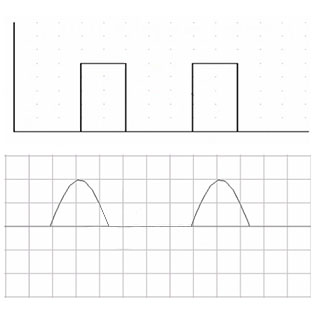
The smaller the duty cycle, the smaller the fundamental component, the larger the higher harmonic component, so the choice of line diameter (penetration depth *2) can not only consider the frequency of the fundamental current.
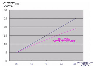
The relationship between output power and frequency (EE25 single-ended converter as an example)
In theory, for a given core, at the same magnetic density, the output power is proportional to the frequency, but in practice it is not.
The reasons are:
(1) Frequency increases, penetration depth decreases, smaller wire diameter is needed, window utilization decreases, and the ratio of winding layer thickness to penetration depth increases, AC resistance increases, and effective output power decreases;
(2) As the frequency increases, the voltage resistance of the insulation material decreases, in order to ensure the same insulation strength, it is necessary to increase the thickness of the insulation layer and further reduce the window utilization rate;
(3) After the frequency reaches a certain degree, the magnetic core loss increases greatly, and the bottom magnetic flux density needs to be properly reduced (please refer to the magnetic loss table for details).
LLC Transformer
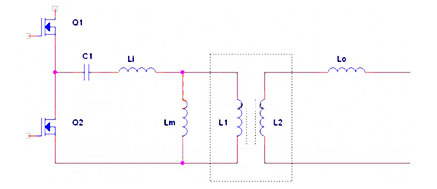
LLC circuit structure
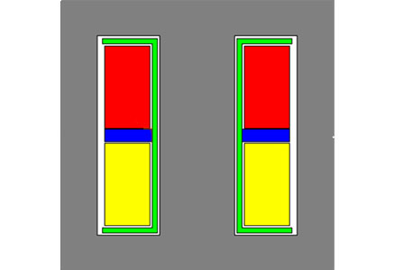
LLC Integrated magnetic component
Leakage is determined by the width of the stop wall between the primary and secondary sides, the permeability of the magnetic core, and the ratio of the length of the middle column to the height of the window.
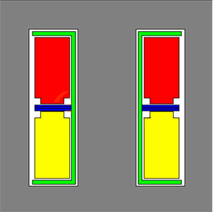
Red: primary winding
Yellow: secondary winding
LLC integrated magnetic element with small leakage sensing
In individual applications, smaller leakage sensing is needed, the width of the retaining wall is small, and the safety spacing can be met by the following structure.
Red: primary winding
Yellow: secondary winding
Other ways to reduce leakage:
(1) the permeability of the magnetic core, replaced by a high-conductivity magnetic core, the leakage will be reduced;
(2) Reduce the ratio between the length of the middle column and the height of the window (referring to the horizontal direction of the window in the above figure), and the leakage will be reduced;
(3) The use of diamagnetic materials instead of paramagnetic materials to make stopper walls;
Methods to increase leakage:
(1) Replace the magnetic core with a low conductivity;
(2) Increase the ratio of the length of the middle column to the height of the window;
(3) The use of weak ferromagnetic materials to make a stop wall, such as injection gaskets mixed with magnetic powder, can greatly reduce the window area of the stop wall and increase the transformer output, and the specific implementation needs to consider economy;
High power LLC transformer
The problem of the LLC magnetic integrated transformer: Because the magnetic field generated by the primary winding is independently distributed, the respective proximity effect is very strong, which is not conducive to high-power applications, and the EMI in the air gap is very difficult to deal with, so the leakage induction needs to be independent.
The medium power LLC lumped parameter transformer is designed according to sinusoidal transformer and can be wound by simple winding process.
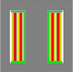
Red: primary winding
Yellow: secondary winding
High-power LLC centralized parameter transformer, according to the sinusoidal transformer design, need to use the sandwich process, the magnetic field of each primary winding magnetic field, reduce the proximity effect, to ensure the minimum AC resistance.
Red: primary winding
Yellow: secondary winding
B. high power density transformer
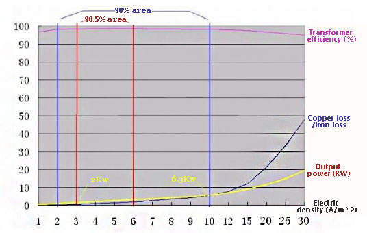
In order to be intuitive, we draw the efficiency, output power, copper and iron loss ratio of an EE85 magnetic core at 2000GS magnetic density and 25KHz frequency at different current densities in the same table (note: because the width is not enough, the ratio of current density above 10 is different).
It can be found that the transformer efficiency reaches more than 98.5% in the range of 3-6A/mm2 current density, and to meet the 98% efficiency, the range of current density reaches 2-10A/mm2.
Since the iron loss is basically fixed, and the copper loss is proportional to the square of the output power, the realization of the high power density transformer is mainly to solve the heat dissipation problem of the winding, but the direction in the application is the opposite, we see the high power density transformer, is the winding heat “stuffy” inside the magnetic parts, the winding thermal resistance is relatively large, is not conducive to improving the power density, such as PQ, PM, and flat transformers.
High power density transformer solution
Idea: the winding is forced to cool
(1) Liquid cooling method
The low-voltage winding is made of hollow tubular copper material, and the micro-shaped hydraulic pump provides cooling circulation liquid for the low-voltage winding, which can be used as transformer oil. The heat energy of the high pressure winding is dissipated to the low pressure winding by conduction and carried away by the coolant.
(2) Ring copper strip winding
The low-voltage winding is made of a flat ring, a ring for one turn, the thickness of the ring is 2 to 3 times the penetration depth, the primary winding wire diameter is 1 to 1.5 times the penetration depth, such a combination of AC resistance is very small. The 6 rings in the legend, through different riveting, can be combined into 6 turns, 3 turns, 2 turns and 1 turns of four connection modes. The chamfering part of the ring is connected with the heat sink (fan can be added) to dissipate heat to solve the heating problem of the winding.
(3)Ring transformer
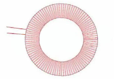
Annular transformer with exaggerated winding heat dissipation area is a very good heat dissipation structure. However, since the best working temperature of the magnetic core is about 90 degrees, the surface temperature of the winding is required to be appropriately less than 90 degrees, otherwise the magnetic core temperature will be too high. In addition, annular high-permeability magnetic parts are easy to fill, and the available magnetic density is small, so the improvement of power density is limited.
(4) Increase the overall surface area of the transformer, such as a planar transformer, by flattening the transformer, improve the ratio of surface area to volume, reduce thermal resistance, and obtain a higher power density.
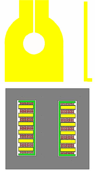
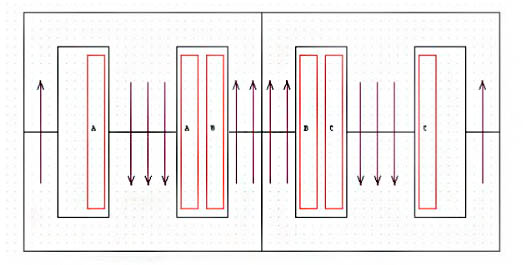
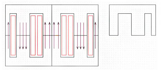
(5) Wang’s multi-magnetic transformer
By combining a number of small magnetic components, the heat dissipation capacity of the transformer windings is greatly improved by nearly twice the number of windings, and high power density is achieved.
For the sake of simplicity, only the two-core combination is taken as an example, and the practical application is more magnetic core combination of multi-magnetic transformer.
(1) The number of windings increases because N is increased to 2N-1(N is the number of combined magnetic cores), and the total (heat dissipation) surface area of the winding increases;
(2) The thickness of each winding is halved, allowing 1.414 times the current density under the same temperature rise and cooling conditions;
(3) It can easily achieve 1/2.1/3.1/4.1/5 or even smaller fractional turns, which is conducive to making the magnetic core work at the best magnetic flux density (under normal circumstances, we often suffer from this problem, such as 2.3 turns are sometimes needed with 1600GS, generally have to take 2 turns, and then increase the magnetic density to 1840GS, or reduce some duty cycle, which is very troublesome);
(4) Because of the precise fractional turns, it is conducive to the accurate voltage distribution of multiple sets of outputs (using synchronous rectification and electronic transformer constant ratio conversion technology);
Optimized multi-circuit transformers and cores
Post time: Nov-05-2024

