When repairing the amplifier circuit of radio, tape recorder, power amplifier, combination speaker, etc., the fault finder can be used to determine the fault location quickly and accurately. It has the characteristics of compact, light and easy to carry, and can be used as a regular tool for electronics enthusiasts.
The circuit is shown in the attached drawing. The probe contacts the measured point, and the received electrical signal is coupled by capacitor C1 to the base of the triode VT1, which is pre-amplified by VT1.
The amplified signal is transmitted to the direct-coupled two-stage amplifier circuit composed of triode VT2, compound tube VT3 and VT4 through the high-frequency choke coil 1, and is output by the emitter of the compound tube to push the speaker Y to make a sound. When the probe contacts the measured point and the Y is silent or the sound is distorted, it indicates that there is a fault in the circuit.
2. Select components
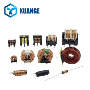
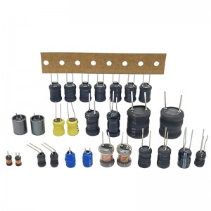
VT1 and VT2 are high gain triode 9014, the penetration current is small, β>80; VT3 and VT4 are 9012, and the beta value can be selected between 50 and 1 00. Inductor 1 and capacitor C2 constitute a high-frequency filter circuit. 1 Choose 10mH color code inductor, model 1H2A, other color code inductors can also be used. Led VD can be arbitrarily selected. The speaker acts as a monitor.
8Ω / 0.1W moving-coil paper basin speaker can be selected, RP is used to adjust the signal size, the resistance value is selected 5.1kΩ, and the switch S is required to be connected. The probe can be modified with a large animal injection needle or a small multimeter pen.
Parameters of other components are marked in the figure without special requirements.
3. VT1 and VT2 operating point adjustment
The part of this circuit that needs to be adjusted is the static operating point of VT1 and VT2. Before adjustment, the potentiometer RP is first rotated in a moderate position, a signal generator is selected, the frequency is 800Hz ~ 1kHz, and the level is in the range of -14 ~ 0dB. The probe contacts the output end of the signal generator and connects the crocodile clip of the device to the ground wire of the signal generator. If there is no signal generator, the probe can be touched to the collector of the radio power amplifier pre-triode. The crocodile clips the radio power supply negative or “ground”. When tuning the radio, speaker Y can hear the broadcast.
Adjustment of VT1 static operating point: When you hear a weak signal, it means that VT1 is in a saturated state, adjust the resistance R1, the signal gradually increases, then VT1 collector potential Vc1, gradually increased, until the sound is clearer, at this time IC1, about 0.6mA, VT1 is in the amplified state, you can stop the adjustment. Be careful not to let Vc1 rise close to the supply voltage, otherwise VT1 will tend to be off. If the signal is not heard, it means that VT1 is in the cutoff state, adjust the resistor R1, so that Vc1 gradually decreases from high potential, so that VT1 enters the amplified state. Signal sound to achieve the best effect.
The static operating point adjustment of VT2 is the same as that of VT1. Adjust the resistance R2, so that the signal will continue to increase from clear, do not adjust the signal to harsh. After the adjustment is completed, adjust the potentiometer RP, you will obviously feel the signal can be large or small. At this time, the measured VT2 collector current Ic2 is 5 ~ 10mA.
It should be noted that when adjusting the resistance R1 and R2, it is best to first string the resistance of 1kΩ and 10kΩ, so as not to accidentally adjust the resistance to 0Ω, the power supply voltage will be added to the base and emitter of VT1 and VT2, thus burning out the transistor. After adjustment, use a multimeter to measure the actual resistance value, and then fix the R1 and R2 resistors.
4. Precautions in use
1, Turn on the power supply (the switch with volume control adjustment), the indicator light VD, you can use.
2, Connect the crocodile clip of the device with the ground wire of the machine to be checked, turn on the power supply of the electrical machine to be checked, and turn on the volume switch of the two to the maximum position.
3, touch the probe respectively at all levels of output. When a certain level is touched, the speaker Y has a signal, indicating that the level and above are normal (the signal in the speaker refers to the signal sent by the radio broadcast, tape sound source or signal generator, etc.).
4, the inspection method generally starts from the first stage, step by step forward, because the final stage signal is strong, in order to prevent over-load distortion, the signal volume can be appropriately reduced.
5, when the measured part is greater than 160V, it should be strung into the corresponding voltage capacitor.
XuanGe Electronic Components Manufacturer
Articles you may be interested in:
▷Infrared radiation alarm circuit
▷Energy saving LED flashlight circuit
▷Simple and practical LED light driver circuit
Post time: Dec-21-2024


