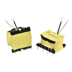
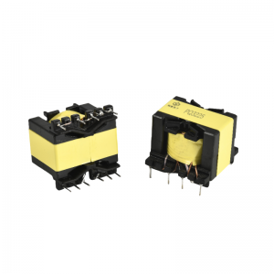
POT3019 High Frequency Power Transformer
Design principle
In the design of high-frequency transformer, the leakage inductance and distributed capacitance of transformer must be minimized, because the high-frequency transformer in switching power supply transmits high-frequency pulse square wave signals. In the transient process of transmission, leakage inductance and distributed capacitance will cause surge current and peak voltage, as well as top oscillation, resulting in increased loss. Usually, the leakage inductance of transformer is controlled as 1% ~ 3% of the primary inductance. Leakage inductance of primary coil-leakage inductance of transformer is caused by incomplete coupling of magnetic flux between primary coil and secondary coil, between layers, and between turns. Distributed capacitance-The capacitance formed between turns of transformer winding, between upper and lower layers of the same winding, between different windings, and between windings and shielding layer is called distributed capacitance. Primary winding-The primary winding should be placed in the innermost layer, so that the length of the wire used in each turn of the transformer primary winding can be shortest, and the wire used in the whole winding can be minimized, which effectively reduces the distributed capacitance of the primary winding itself. Secondary winding-After the primary winding is wound, it is necessary to add (3 ~ 5) layers of insulation lining before winding the secondary winding. This can reduce the capacitance of the distributed capacitor between the primary winding and the secondary winding, and also increase the insulation strength between the primary winding and the secondary winding, which meets the requirements of insulation and voltage resistance. Bias winding-whether the bias winding is wound between the primary and secondary or the outermost layer is related to whether the adjustment of the switching power supply is based on the secondary voltage or the primary voltage.


